Securing electronic devices within a sub-chassis for connection to a chassis midplane

a technology of electronic devices and chassis, applied in the direction of metal working apparatus, support structure mounting, manufacturing tools, etc., can solve the problems of electronic noise becoming more of a concern, low-speed and low-voltage signals are more susceptible to electronic noise disruption than low-speed and high-voltage signals, and electronic noise relates to conductive stubs

Active Publication Date: 2014-07-03
LENOVO GLOBAL TECH INT LTD
View PDF1 Cites 0 Cited by
  • Summary
  • Abstract
  • Description
  • Claims
  • Application Information

AI Technical Summary

Problems solved by technology

As the frequency of electronic signals continues to increase, and as the voltages associated with these signals decreases, electronic noise becomes more of a concern.
High-speed and low-voltage signals are more susceptible to electronic noise disruption than are low-speed and high-voltage signals.
One source of electronic noise relates to conductive stubs.
The stub is not in a direct conductive pathway between the true point of contact and the electronic device, and is not a useful part of the circuit.
However, a stub of this type can be the source of unwanted electronic signal reflections in a high-speed, low-voltage electronic signal.
To ensure conductive engagement, the pads along the card edge are generally elongate along the direction of the card edge insertion so that any variance in the dimensions of the circuit board, socket, or relevant chassis does not prevent conductive contact between the pads and the signal pins.

Method used


Image

  • Securing electronic devices within a sub-chassis for connection to a chassis midplane
  • Securing electronic devices within a sub-chassis for connection to a chassis midplane
  • Securing electronic devices within a sub-chassis for connection to a chassis midplane

Examples


Embodiment Construction

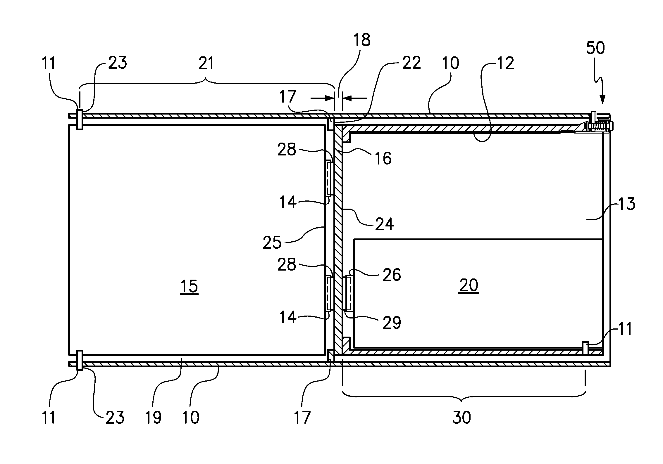
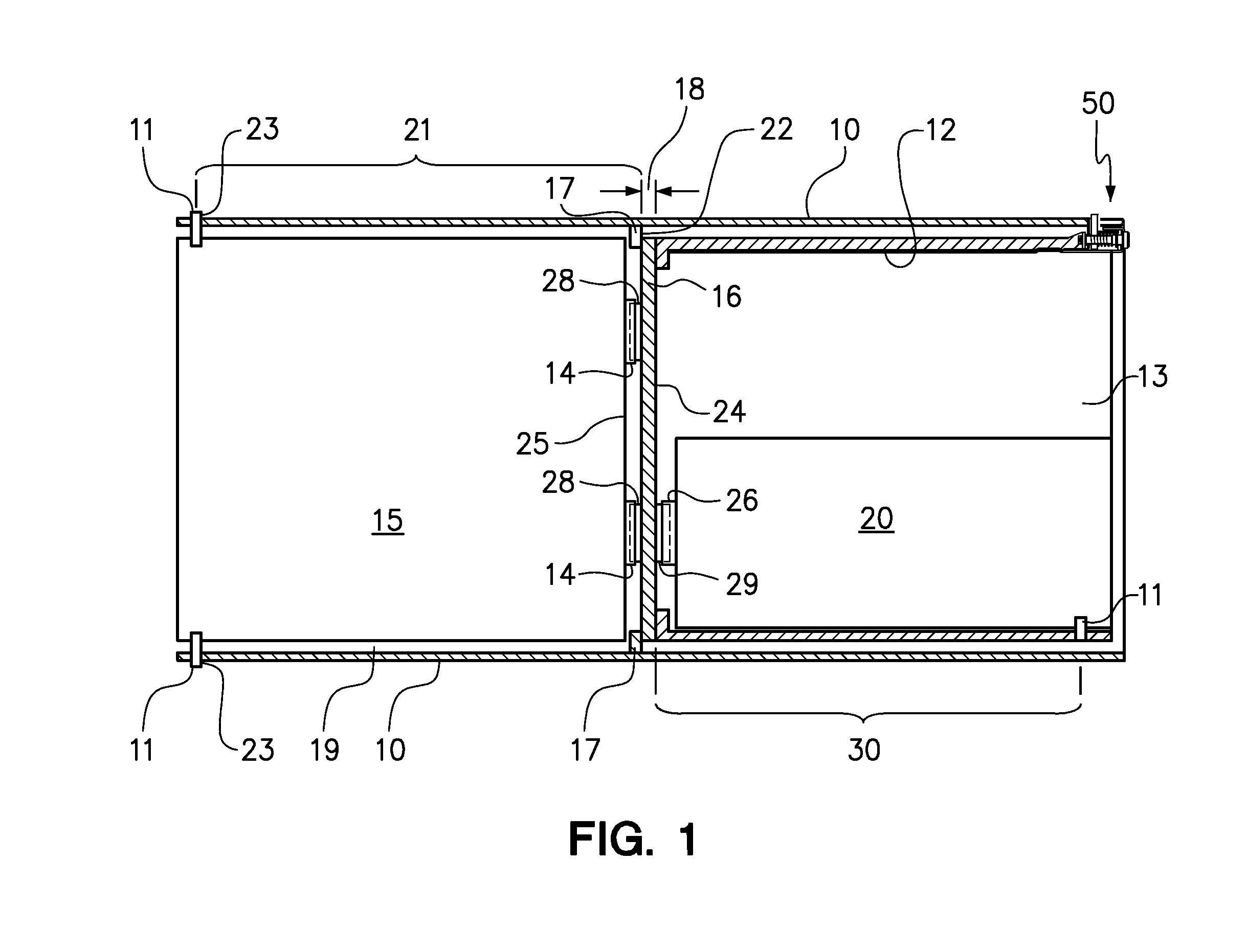
[0019]One embodiment of the present invention provides an apparatus comprising a chassis and a sub-chassis. The chassis has a first end, a second end, a bracket between the first and second ends, a first slot adjacent the first end, and a second slot adjacent the second end. The bracket is positioned for securing a first surface of a midplane at a known distance from the first slot, wherein a first electronic device is selectively securable within the first end of the chassis with a first device connector coupled to the first surface of the midplane and a first device latch secured to the first slot. The sub-chassis is receivable within the second end of the chassis, wherein the sub-chassis has a proximal end that engages a second surface of the midplane, a distal end having a sub-chassis latch that selectively engages the second slot to secure the sub-chassis in the second end of the chassis with the proximal end engaged against the second surface, and a sub-chassis slot adjacent t...


PUM

PropertyMeasurementUnit
reactive forceaaaaaaaaaa
conductiveaaaaaaaaaa
frequencyaaaaaaaaaa

Abstract

A method includes securing a midplane to a bracket disposed between a first and second ends of a chassis, wherein a first surface of the midplane engages the bracket and faces the first end of the chassis. A first electronic device is secured within the first end of the chassis with a first device connector coupled to a first midplane connector on the first surface of the midplane and a first device latch secured directly to a first slot in the chassis adjacent the first end. A sub-chassis is secured within the second end of the chassis, wherein the sub-chassis has a proximal end that engages a second surface of the midplane. Furthermore, a second electronic device is secured within the sub-chassis with a second device connector coupled to a second midplane connector on the second surface of the midplane and a second device latch secured directly to a slot in the sub-chassis adjacent the distal end of the sub-chassis.

Description

CROSS-REFERENCE TO RELATED APPLICATIONS[0001]This application is a continuation of co-pending U.S. patent application Ser. No. 13 / 729,349, filed on Dec. 28, 2012.BACKGROUND OF THE INVENTION[0002]1. Field of the Invention[0003]The present invention relates to an apparatus to position and secure a sub-chassis within a chassis.[0004]2. Background of the Related Art[0005]An electronic device within a computer system may be connected to other electronic components through connectors that enable the communication of data signals therebetween. For example, a first electronic device, having a connector thereon, may send signals through the connector and to a second electronic device also having a connector that is engaged by the connector on the first electronic component. Connectors come in a variety of configurations including, but not limited to, pin and socket connectors, pin and sleeve connectors, parallel port, USB and serial connectors, to name a few. The connectors of the first elec...

Claims


Application Information

Patent Timeline
Patent Type & Authority Applications(United States)
IPC IPC(8): H05K13/04
CPCH05K13/04H05K7/1489Y10T29/49826Y10T29/4913Y10T29/49144
Inventor DITTUS, SR., KARL K.JENSEN, DAVID J.TRUMBO, BRIAN A.
Owner LENOVO GLOBAL TECH INT LTD
Why Eureka
Try Eureka