
Roof element

a technology of roof elements and elements, applied in the field of roof materials, can solve problems such as double overlap at one corner

Inactive Publication Date: 2014-07-10
NICHOLSON JOSEPH ROBERT
View PDF1 Cites 12 Cited by
  • Summary
  • Abstract
  • Description
  • Claims
  • Application Information

AI Technical Summary

Benefits of technology

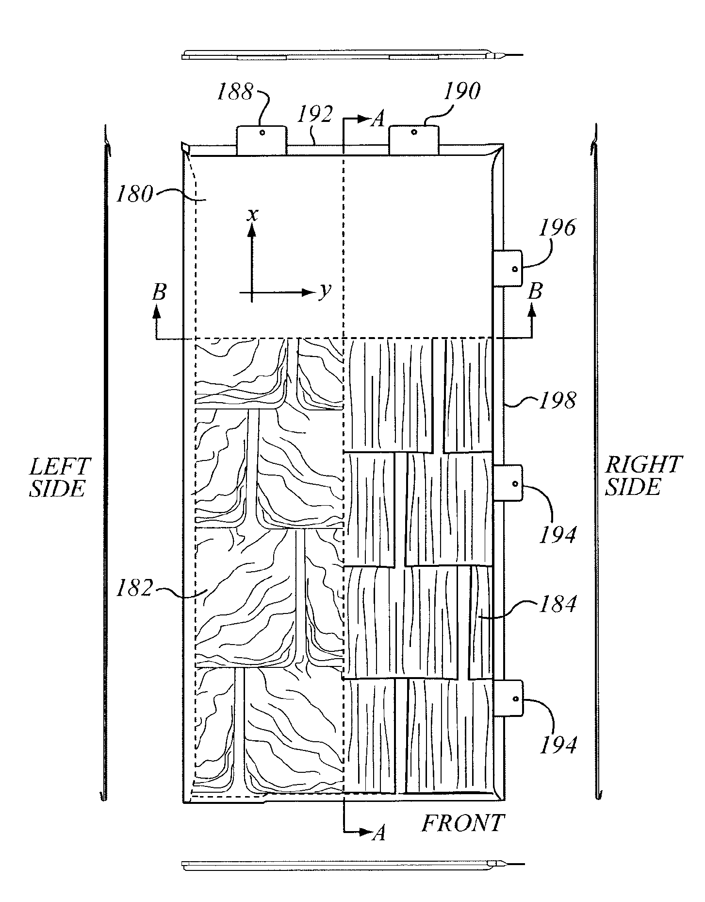
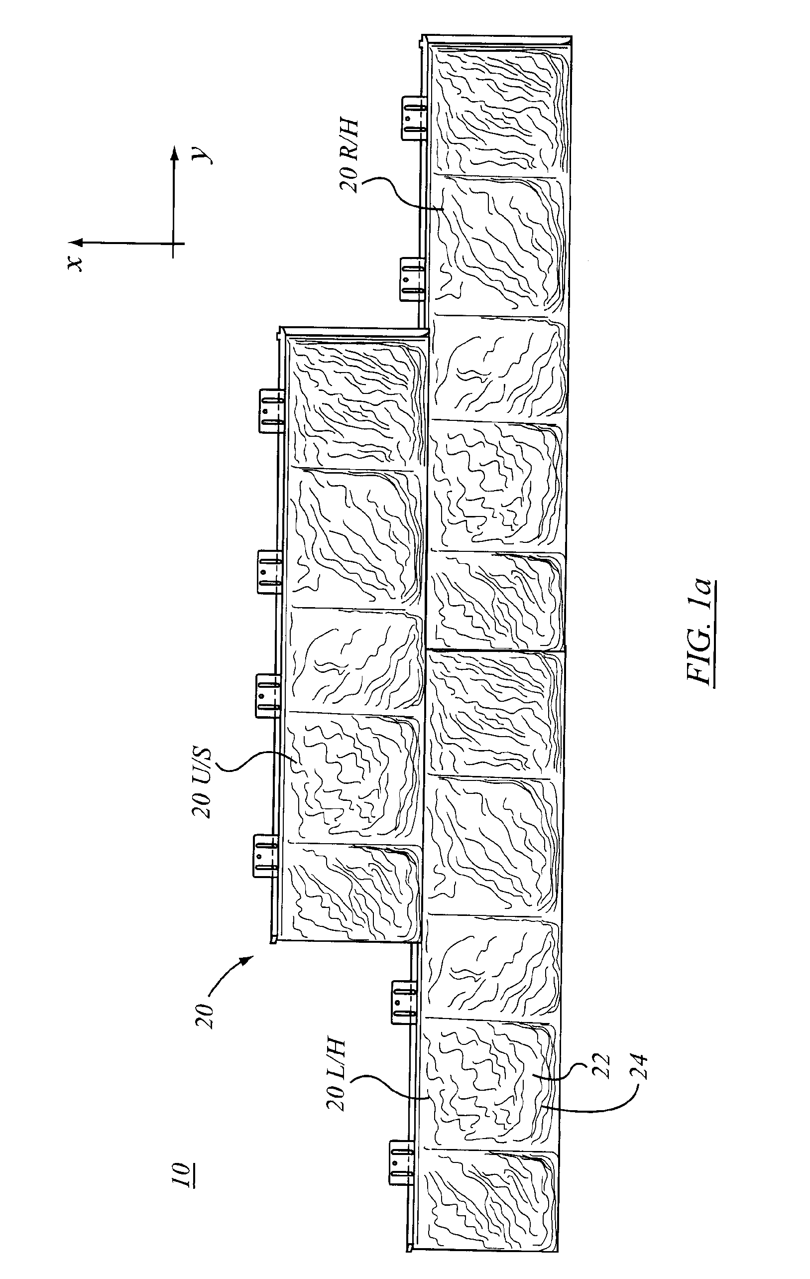
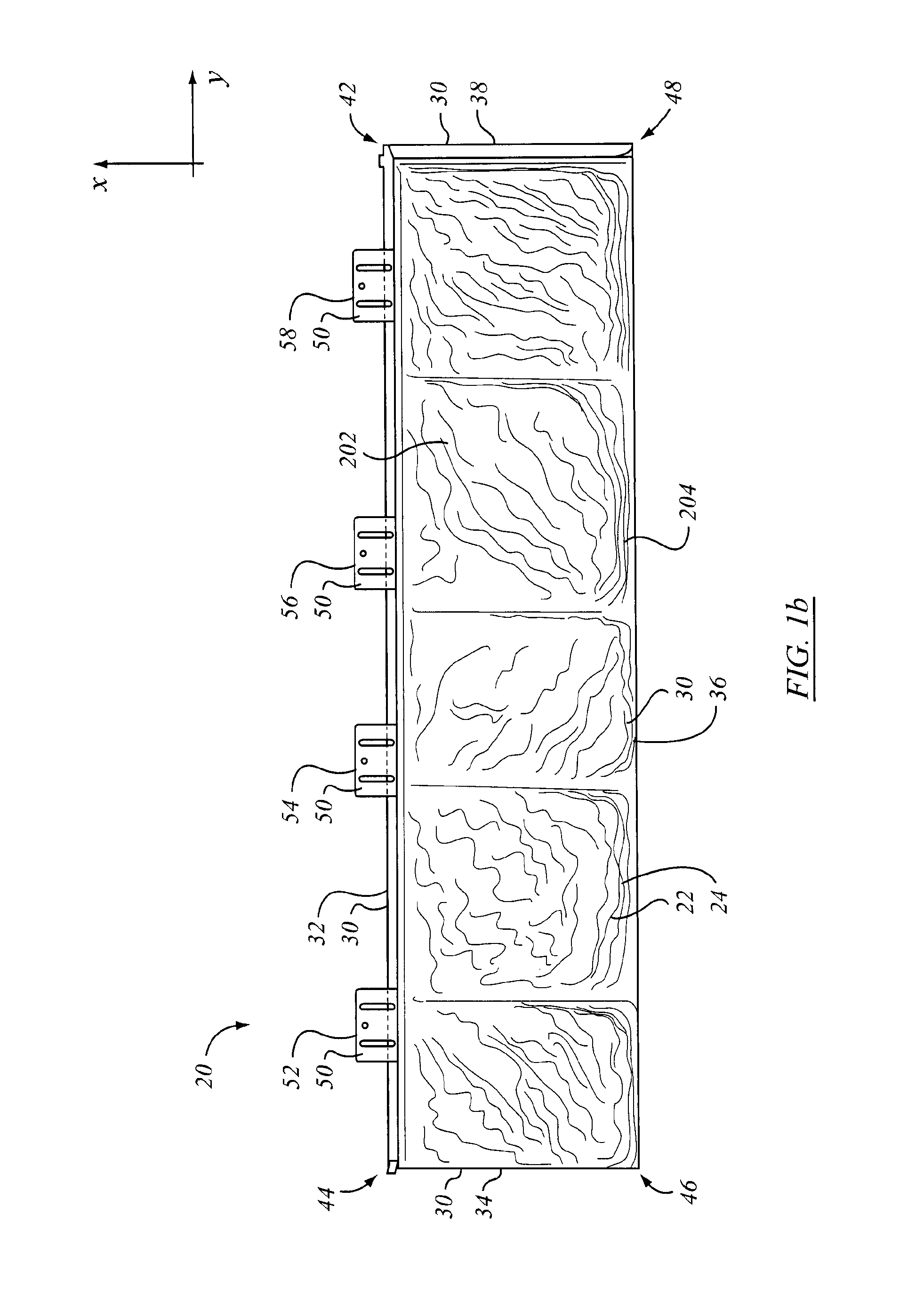
The invention is a roofing element for mounting on a sloped roof that has a formed panel with a cross-slope width and a slope-wise length. The panel has a top edge margin, a bottom edge margin, a first side edge margin, and a second side edge margin. The top edge margin has an upwardly formed over-folded flange with a distal flange edge oriented down-slope. The bottom edge margin has a downwardly formed under-folded flange with a distal flange edge oriented up-slope. The panel also has a relief pattern formed therein that simulates a wooden shake or slate tile. The roofing element has a first margin and a second margin. The first margin is an up-slope margin, while the second margin is a down-slope margin. The first and second margin have a fastener securement portion for concealment under a next adjacent up-lope roofing element upon installation on a roof. The panel also has a second relief feature formed therein that has a flank surface with a gentle rise-over-run in the length direction.

Problems solved by technology

Another common problem with metal shingles is the issue of the double overlap at one corner.

Method used


Image

  • Roof element
  • Roof element
  • Roof element

Examples


Embodiment Construction

[0036]The description that follows, and the embodiments described therein, are provided by way of illustration of an example, or examples, of particular embodiments of the principles of the present invention. These examples are provided for the purposes of explanation, and not of limitation, of those principles and of the invention. In the description, like parts are marked throughout the specification and the drawings with the same respective reference numerals. The drawings are generally in proportion, though perhaps not precisely to scale, and may be taken as being roughly to scale except where noted otherwise, such as in those instances in which proportions may have been exaggerated in order more clearly to depict certain features of the invention.

[0037]Following from Phillips v. AWH Corp., definitions provided in the specification are intended to supplant any dictionary definition, and to prevent interpretation in the US Patent Office (or in any other Patent Office) that strays...


PUM


Abstract

A roofing element for mounting on a sloped roof includes a formed panel. In one embodiment the length is at least as great as the width, the width being cross-wise relative, the length running down the slope. The formed panel has a relief pattern that has a grain direction aligned with the length. The width may be less than one arm's length. The relief element simulates a wooden shake or a slate tile. The sheet metal panel has top, bottom, and first and second side edge margins. The top edge margin has a bulge at one end, and a matingly sized double cuff at the other end. The next adjacent side has a relieved upper end flange that has a transition from a flat flange to a narrower upstanding curved wall defining the lower edge of an accommodation permitting the double cuff of one panel to seat in the mating accommodation of the next adjacent panel. When installed, the accommodation and the double cuff are overlain by the bottom edge margin flange of the next up-slope tile.

Description

FIELD OF THE INVENTION[0001]This invention relates to roofing materials, and in particular to roofing elements such as may form the surface of the roof exposed to the weather.BACKGROUND OF THE INVENTION[0002]In North America asphalt shingles are used as the surface elements of many inclined roofs. However other materials are known, such as wooden shakes, such as cedar shakes; clay tiles; and metal roofing panels. In agricultural or industrial applications, relatively long, corrugated metal sheets of constant section, or hat sections have been long known. However, metal or plastic roofing tiles may also be provided in smaller sections, those sections having a stamped contour or texture. The stamped texture may be intended to simulate the pattern of, for example, asphalt shingles. Alternatively, they may have a pattern resembling slates or tiles. In a further alternative, they may have the general appearance of wooden shakes, such as cedar shakes.[0003]Another common problem with meta...

Claims


Application Information

Patent Timeline
Patent Type & Authority Applications(United States)
IPC IPC(8): E04D1/26E04D13/00E04B7/02
CPCE04D1/18E04D1/265E04D3/30E04B7/02E04D13/00Y10T428/24355E04D1/2949E04D1/2914E04D1/2942
Inventor NICHOLSON, JOSEPH ROBERT
Owner NICHOLSON JOSEPH ROBERT
Learn More