Wire electric discharge machine having function of compensating position of wire electrode

a wire electrode and wire electrode technology, applied in the direction of machine control, process control, instruments, etc., can solve the problems of deterioration of machining accuracy, change of pressure of ejected machining fluid, and inability to become stable in the machining field

Inactive Publication Date: 2014-07-17
FANUC LTD
View PDF15 Cites 9 Cited by
  • Summary
  • Abstract
  • Description
  • Claims
  • Application Information

AI Technical Summary

Problems solved by technology

However, if electric discharge machining is carried out while the machining chips are present at the portion to be machined, machining does not become stable.
Accordingly, the ejection of the machining fluid from the upper and lower nozzles 1 and 2 with a high pressure is essential to stable machining, but there is a problem in that the ejection of the machining fluid from the upper and lower nozzles 1 and 2 with a high pressure causes the deterioration of machining accuracy.
However, since the pressure of the ejected machining fluid is changed depending on the shape, machining shape, and machining condition of the workpiece 4, the pressure of the ejected machining fluid is not constant and is changed during machining.
For this reason, even though the pressure of the machining fluid is measured in advance, the pressure of the machining fluid ejected at the time of measurement may be different from the pressure of the machining fluid ejected during actual machining and it is not possible to cope with the change of the pressure of the machining fluid during machining.
Accordingly, it is not possible to continue to compensate displacement that is caused by an appropriate pressure of the machining fluid.
Furthermore, there is a possibility that an amount of compensation is erroneously set due to a measurement error when the displacement amounts of the upper and lower nozzles 1 and 2 are measured.
Accordingly, there is a problem in that the compensation method is not realistic.

Method used


Image

  • Wire electric discharge machine having function of compensating position of wire electrode
  • Wire electric discharge machine having function of compensating position of wire electrode
  • Wire electric discharge machine having function of compensating position of wire electrode

Examples


Embodiment Construction

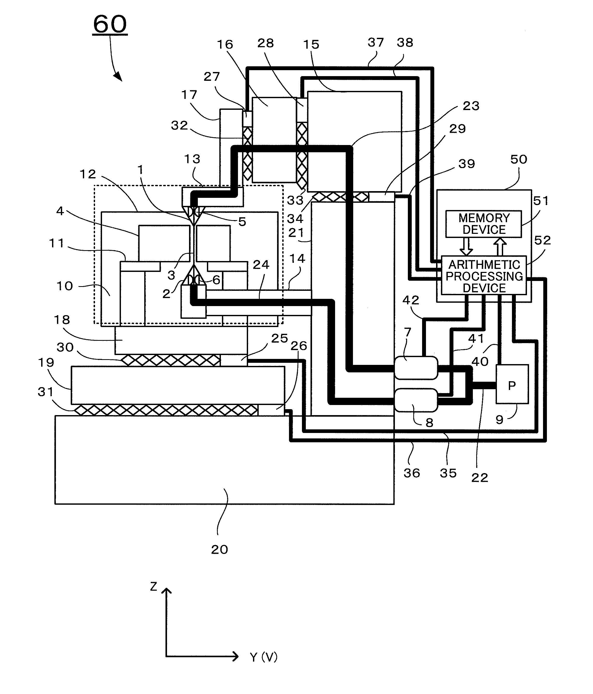
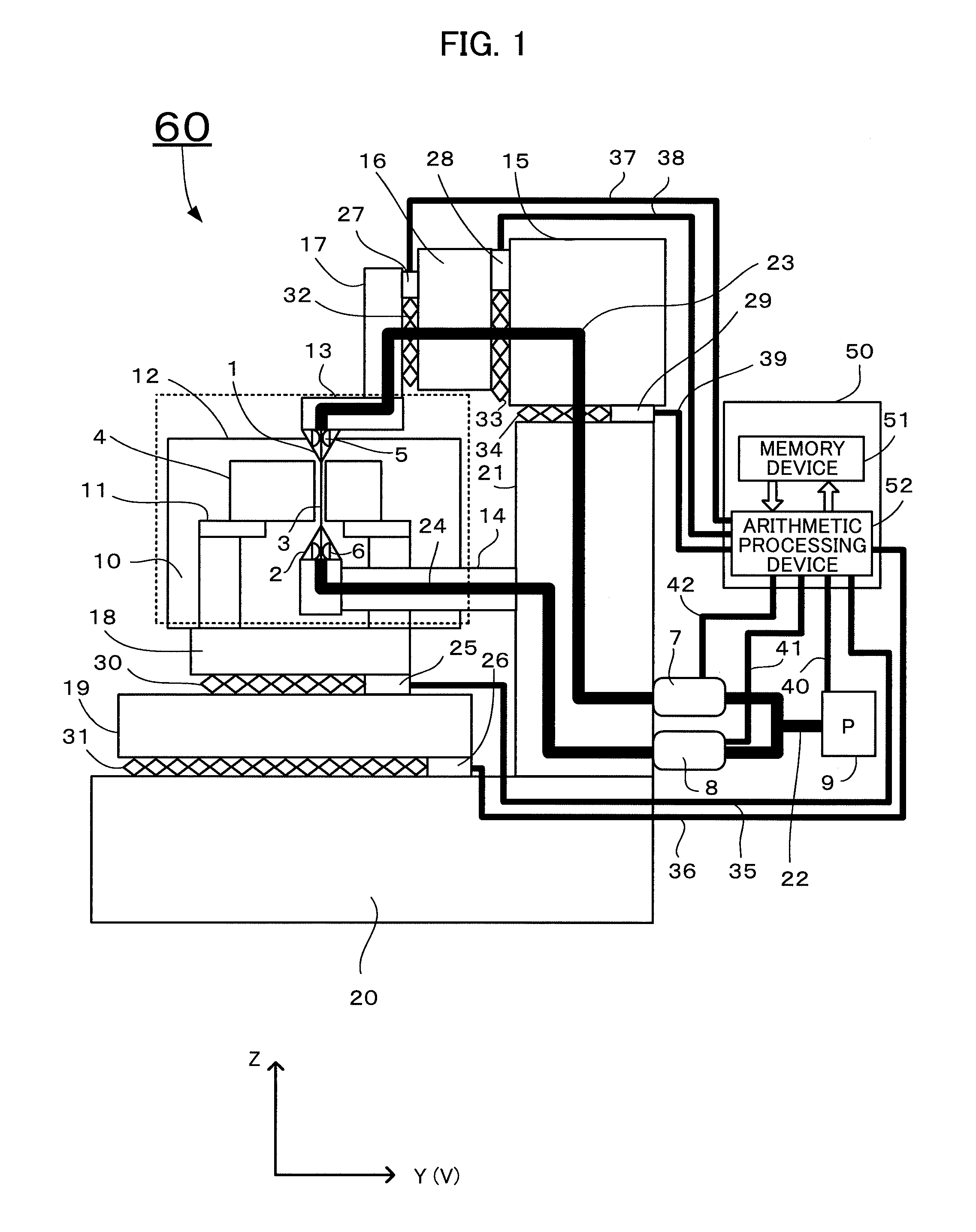
[0023]A wire electric discharge machine according to an embodiment of the invention will be described with reference to FIG. 1.

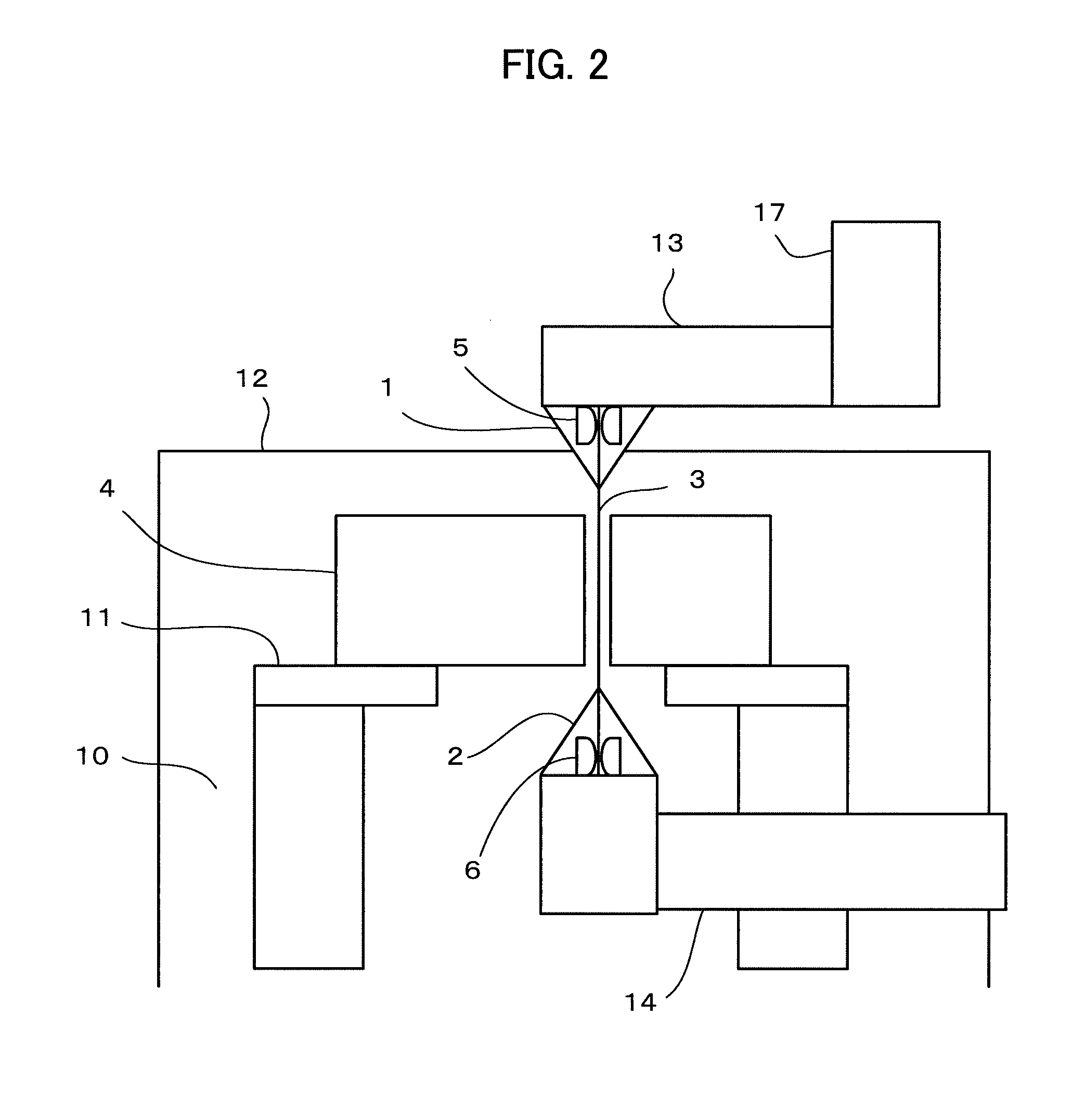
[0024]A wire electric discharge machine 60 performs the machining of a workpiece 4 by generating electric discharge between a wire electrode 3 and the workpiece 4. The wire electric discharge machine 60 includes a saddle (X axis) 19 that is provided on a bed 20 and is moved in an X-axis direction by a ball screw 31 driven by an X-axis motor 26, and further includes a table (Y axis) 18 that is provided on the saddle (X axis) 19 and is moved in a Y-axis direction by a ball screw 30 driven by a Y-axis motor 25. A machining tank 12 including a workpiece mounting stand 11, which is provided therein and on which the workpiece 4 is placed, is fixed onto the table (Y axis) 18.

[0025]A column 21 is vertically erected on the bed 20. A lower arm 14 is horizontally mounted on the side surface of the column 21. A lower nozzle 2 and a lower wire guide 6 are mounted on the ...


PUM

PropertyMeasurementUnit
pressureaaaaaaaaaa
repulsive forceaaaaaaaaaa
displacementaaaaaaaaaa

Abstract

While machining is carried out according to a machining program by an electric discharge machine, the pressures of a machining fluid supplied from upper and lower nozzles are detected and displacement amounts of upper and lower wire guides are obtained from the detected pressures. Further, positional compensation values of the upper and lower wire guides are calculated on the basis of the obtained displacement amounts, and command values of the machining program are compensated on the basis of the calculated positional compensation values.

Description

BACKGROUND OF THE INVENTION[0001]1. Field of the Invention[0002]The present invention relates to a wire electric discharge machine having a function of compensating the displacement of a wire electrode that is caused by the pressure of a machining fluid.[0003]2. Description of the Related Art[0004]A positional relation between a wire electrode and a workpiece in a wire electric discharge machine in the related art will be described with reference to FIG. 3.[0005]The wire electric discharge machine performs the machining of a workpiece 4 by generating electric discharge between a wire electrode 3 and the workpiece 4. A workpiece mounting stand 11 on which the workpiece 4 to be machined by electric discharge machining is placed is disposed in a machining tank 12 that stores a machining fluid 10.[0006]An upper nozzle 1 ejects the machining fluid from the upper side of the workpiece 4. A lower nozzle 2 ejects the machining fluid from the lower side of the workpiece 4. An upper wire guid...

Claims


Application Information

Patent Timeline
Patent Type & Authority Applications(United States)
IPC IPC(8): B23H7/06
CPCB23H7/065B23H7/18G05B19/404G05B2219/45043B23H7/10B23H7/20B23H7/101
Inventor YOSHIZAKI, DAISUKEMAKINO, YOSHINORI
Owner FANUC LTD
Why Eureka
Try Eureka