
Electrical Connector

a technology of electrical connectors and connectors, applied in the direction of coupling contact members, coupling device connections, electrical apparatus, etc., can solve the problems of accidental disengagement of connectors, excessive stress on connections, and the ability of pivoting to release, so as to avoid angular movement, resist decoupling, and resist the effect of pivoting

Active Publication Date: 2014-07-17
ITT MFG ENTERPRISES LLC
View PDF2 Cites 11 Cited by
  • Summary
  • Abstract
  • Description
  • Claims
  • Application Information

AI Technical Summary

Benefits of technology

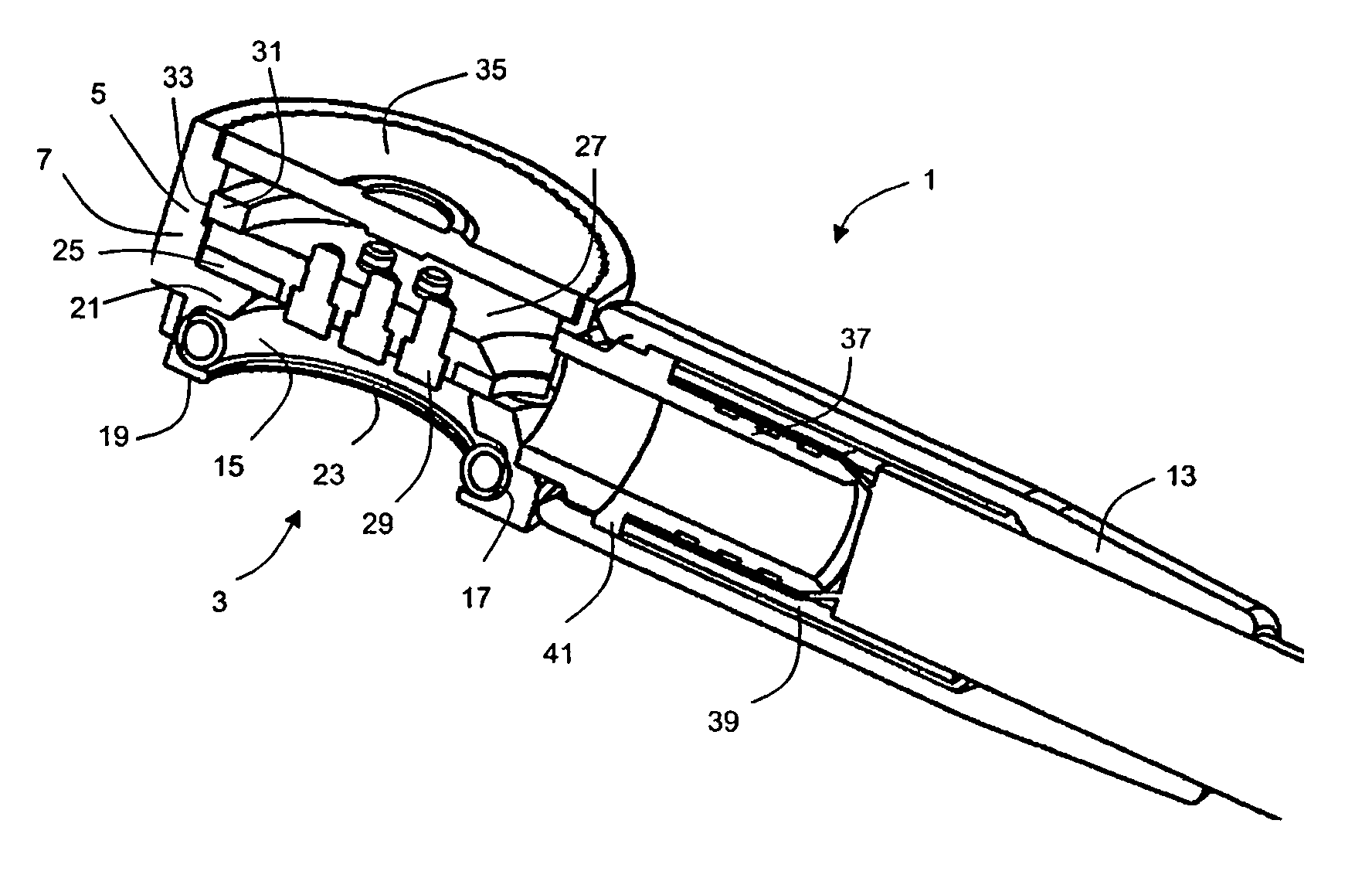
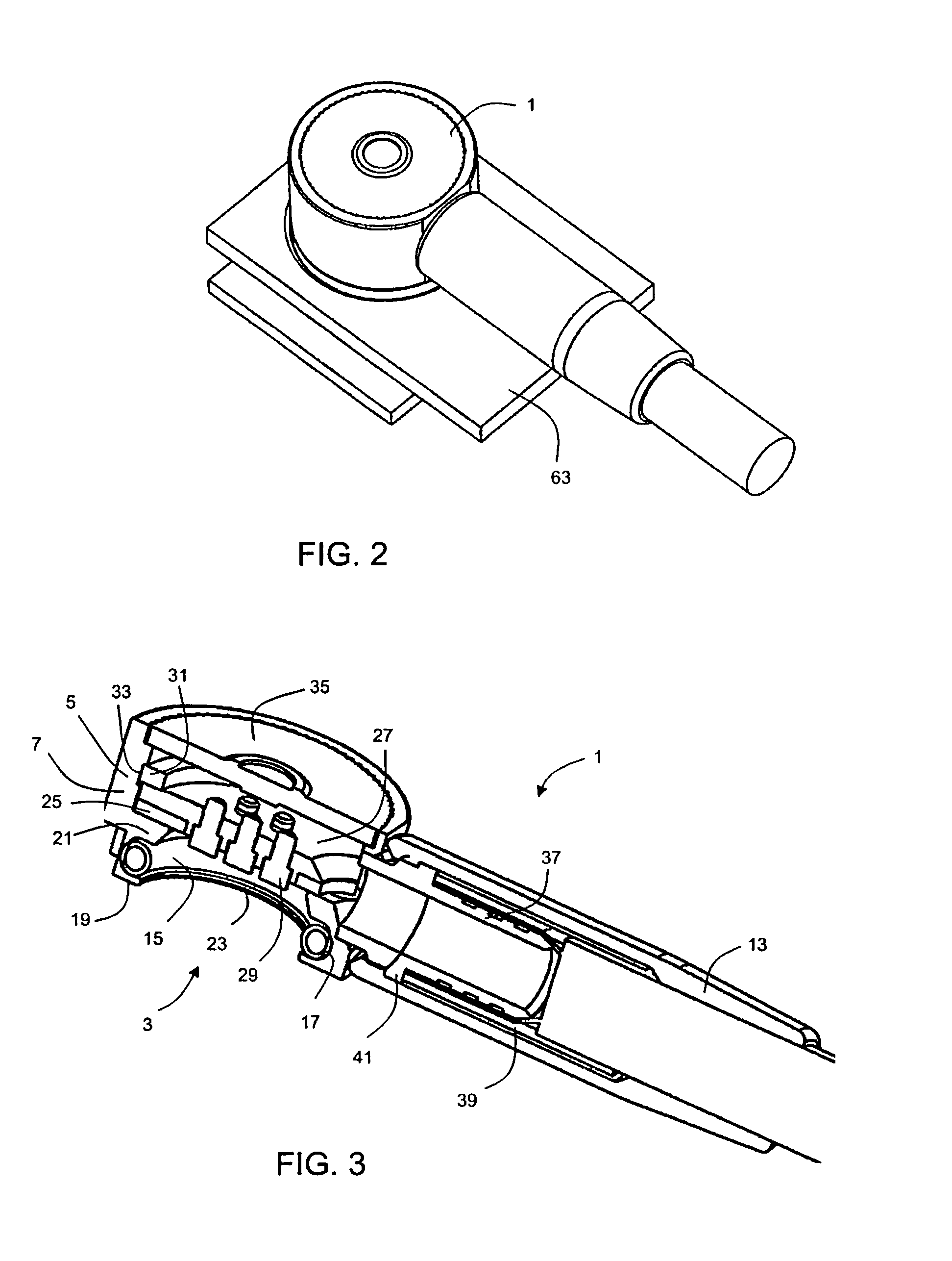
The design uses a sleeve with a cylindrical part near its deepest point to prevent the electrical connector from being released by pivoting. Instead, the release needs to be provided by a force along the direction of the sleeve. This is particularly useful for connection to moving objects such as clothing, where lateral forces are likely to be applied to the connector. The cylindrical portion is long enough to resist pivoting movement of the mated other connector part, but short enough to limit the overall increase in length of the connection.

Problems solved by technology

A problem associated with the known breakaway connector arrangement disclosed in U.S. Pat. No. 2,761,111 is that tension on the electrical cable can lead to accidental disengagement of the connectors.
Furthermore, tension applied on the cable for deliberately disengaging the connectors may cause excessive stress on the connections and lead to damage.
For example, if one of the connectors is mounted in a flexible panel such as an item of clothing, a force resulting in the pivoting release can arise by accident.

Method used


Image

  • Electrical Connector
  • Electrical Connector
  • Electrical Connector

Examples


Embodiment Construction

[0036]The subject matter of the present invention is described with specificity herein to meet statutory requirements. However, this description is not intended to limit the scope of this patent. Rather, it is contemplated that the claimed subject matter might also be embodied in other ways, to include different elements or combinations of elements similar to the ones described in this document, in conjunction with other present or future technologies

[0037]The invention provides an angled electrical connector for terminating an electrical cable and for engaging with a mating electrical connector.

[0038]The invention provides various modifications to the applicant's previous design of GB 2 477 987 to make the design suitable for use when connecting to a fabric article having one connector part provided at its surface. The particular problem of connections to fabric articles (such as a vest) is that the amount of movement in use, and the likelihood of knocking the connection against ot...


PUM


Abstract

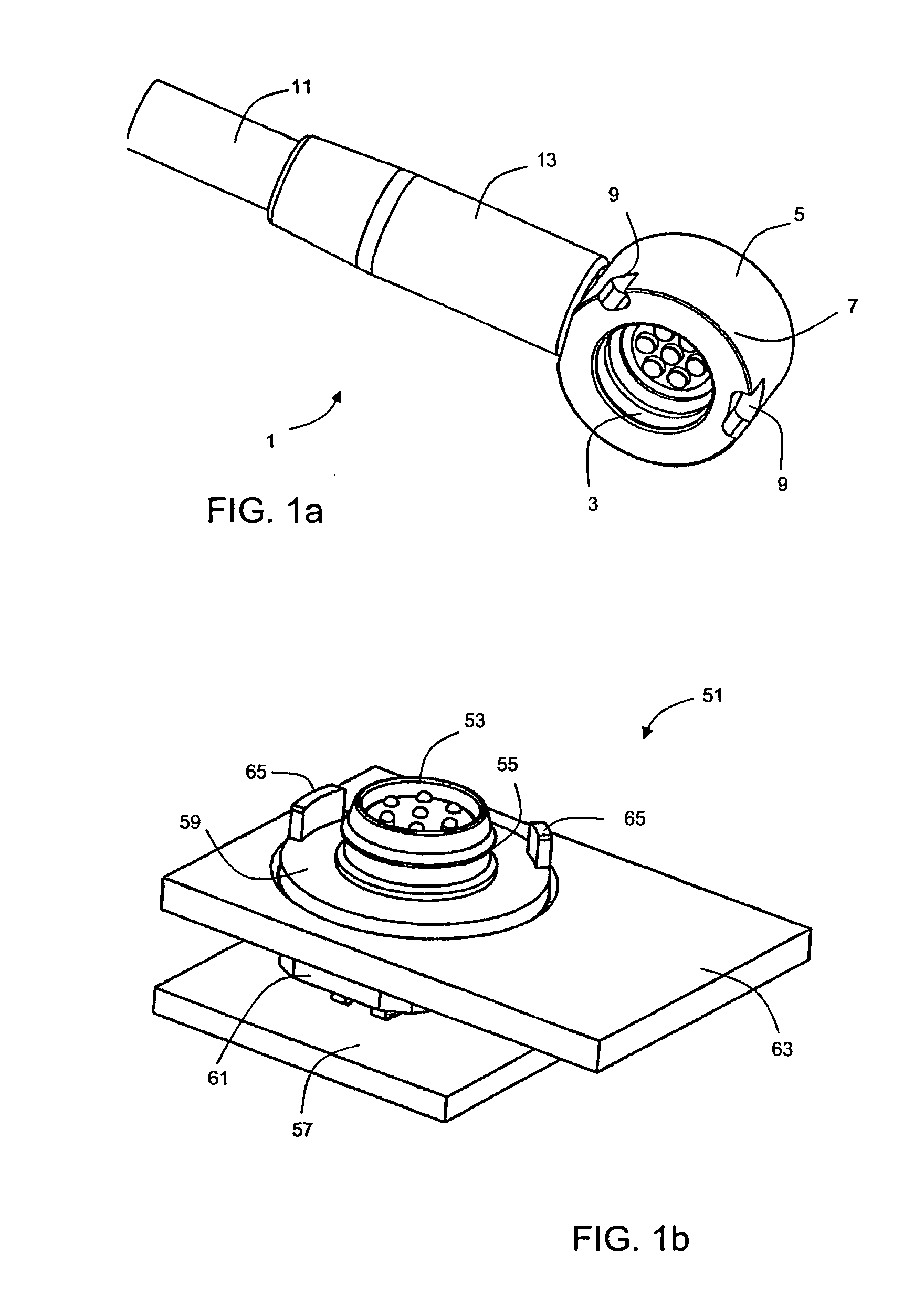
An angled electrical connector has a body having an engagement portion including a sleeve which extends in a longitudinal first direction for engaging with a mating electrical connector. The sleeve has a cylindrical inner portion at the base of the sleeve and a tapered portion, such that the opening of the sleeve is larger than the base. A corresponding receptacle part is also provided, having a projecting connection port, with a corresponding cylindrical portion at or near the end.

Description

CROSS-REFERENCE TO RELATED APPLICATIONS[0001]This application claims priority under 35 U.S.C. §119(a) to GB 1300845.3, which is entitled “Electrical Connector” and was filed Jan. 17, 2013 in UK Intellectual Property Office. The entirety of the aforementioned application is incorporated by reference herein.TECHNICAL FIELD[0002]This invention relates to an electrical connector for terminating an electrical cable, such as a shielded cable. In particular, the invention relates to a so-called “breakaway” connector, which can be firmly engaged with a mating connector but can be quickly and easily disengaged when required.BACKGROUND[0003]U.S. Pat. No. 2,761,111 discloses a known breakaway electrical connector for terminating an electrical cable. The electrical connector is arranged to be mechanically engagable with a mating electrical connector to provide an electrically conductive path from the electrical cable to the mating connector. The connectors can be firmly engaged but quickly and ...

Claims


Application Information

Patent Timeline
Patent Type & Authority Applications(United States)
IPC IPC(8): H01R13/514
CPCH01R13/514H01R13/6277H01R13/6456H01R13/5841H01R13/631
Inventor JORDAN, PETER
Owner ITT MFG ENTERPRISES LLC
Learn More