Sexual Aid System

a technology of aid system and belt, applied in the field of articles, can solve the problems of uncomfortable and inconvenient use of straps and belts, inability to adapt to provide sexual stimulation, and other inconvenient components of belt-engaged devices, so as to improve bias contact, increase sexual stimulation, and increase the effect of users

Active Publication Date: 2014-08-14
DE ALVA JOHN
View PDF1 Cites 24 Cited by
  • Summary
  • Abstract
  • Description
  • Claims
  • Application Information

AI Technical Summary

Benefits of technology

[0025]Additionally preferred in an enhanced mode of the device is a means for user-configuring of the shape of the U-shaped member to increase sexual stimulation. In this mode, a plurality of malleable or bendable points are provided along the coaxial positioned skeletal structure. This allows the user a means for bending or articulating the skeletal component and thereby the surrounding skin of the device and thereby allow for exact positioning of the proximal end upon the G-spot. The user-configurable skeletal component also provides a means for adjusting the width of separation of the distal and proximal ends and the biasing force of both ends of U-shaped member towards each other. In this fashion, the user is afforded a means for achieving a better biased contact of the proximal end with the G-spot and the distal end against the lower abdominal wall and clitoral area of the wearing female. The combination of the biasing of both ends toward each other, and the adjusting of the width, shape, and positioning of the U-shaped member, thereby increases the users sexual stimulation in a customizable fashion and allows the device to be easily retained in the wearer without belts or other mounting devices from the clamping action which is also enhanced.
[0026]In other preferred modes the skeletal component may be formed of a continuous length articulateable material, such as resilient flat or rounded spring steal or other suitable material. Thus the device can be manufactured with less cost due to the singular skeletal member, albeit being suitably bendable and malleable, while the user is still provided with means for user-configuring of the shape of the U-shaped member and means for adjusting the width of separation.
[0027]The head portion of the device, located at the proximal end, is preferably shaped to stabilize the device by intra vaginal surface contact within the anatomic ledge formed above the pubic symphysis of the female wearing the device. The undersurface of this intra vaginal positioned head the U-shaped member is in continuous biased contact with the G-spot thereby providing direct physical stimulation thereto in a motion-energy transfer from the movement of either the wearer's hand on the device or movement of a sexual partner engaged upon the elongated member attached to the U-shaped member.
[0028]The distal end of the U-shaped member provides the user wearing the device constant physical contact and stimulation of the clitoral area with the exterior surface of the U-shaped member through the force and movement communicated from the sexual partner engaged upon the elongated member, or the wearer's hand upon the elongated member. An optional ribbed portion of the external surface, adjacent to the distal end of the U-shaped member, provides a means for increasing physical stimulating of the clitoral area. Thus, the device may be employed for increased sexual stimulation by the wearer alone imparting force to the elongated member, or by a partner through the movement of each other during intercourse and the resulting transfer of force and motion to the device.
[0029]A bifurcating ridge on an inner portion of the external surface of the U-shaped member, adjacent to the proximal end, serves to provide additional physical contact with the G-spot area and is especially preferred. The ridge projects away from the center axis of the U-shaped member a distance to allow it to bury into the flesh of the user in the G-spot area slightly more than the adjacent exterior surface.
[0030]Also preferred in a mode of the device, at a point adjacent to the distal end of the U-shaped member formed by a bend of the U-shaped member, is a hooked portion. The hooked portion is a portion of the member positioned intra vaginally, which bends inward toward the distal end at an increased angle. In use, the hooked portion provides an increased contact force at the proximal end of the U-shaped member within the anatomic ledge when positioned above the pubic symphysis. This hooked contact provides means for increasing the surface contact force with the G-spot while simultaneously providing a more stable clamping engagement of the device caused by the biasing of both ends toward each other.

Problems solved by technology

Such devices however employ straps and belts and other inconvenient components to remain mounted on the one female while being employed upon the other.
They are as such, uncomfortable and inconvenient.
Further, these belt-engaged devices are generally not designed nor adapted to provide sexual stimulation to either individually or to both parties during their physical engagement.
Thus, the sexual satisfaction of the party wearing the device, or in many cases on the receiving end of the device, can be severely lacking.
Without the aid of straps and belts and mounts, or well-coordinated timing during employment of unmounted devices by both parties, disengagement and frustration will generally prevail.
The task of changing device may at be unfavorable for one partner or the other and is therefor an additional downfall with conventional device known in the art.
Various limitations of the related art will become apparent to those skilled in the art upon a reading and understanding of the specification below and the accompanying drawings.

Method used


Image

  • Sexual Aid System
  • Sexual Aid System
  • Sexual Aid System

Examples


Embodiment Construction

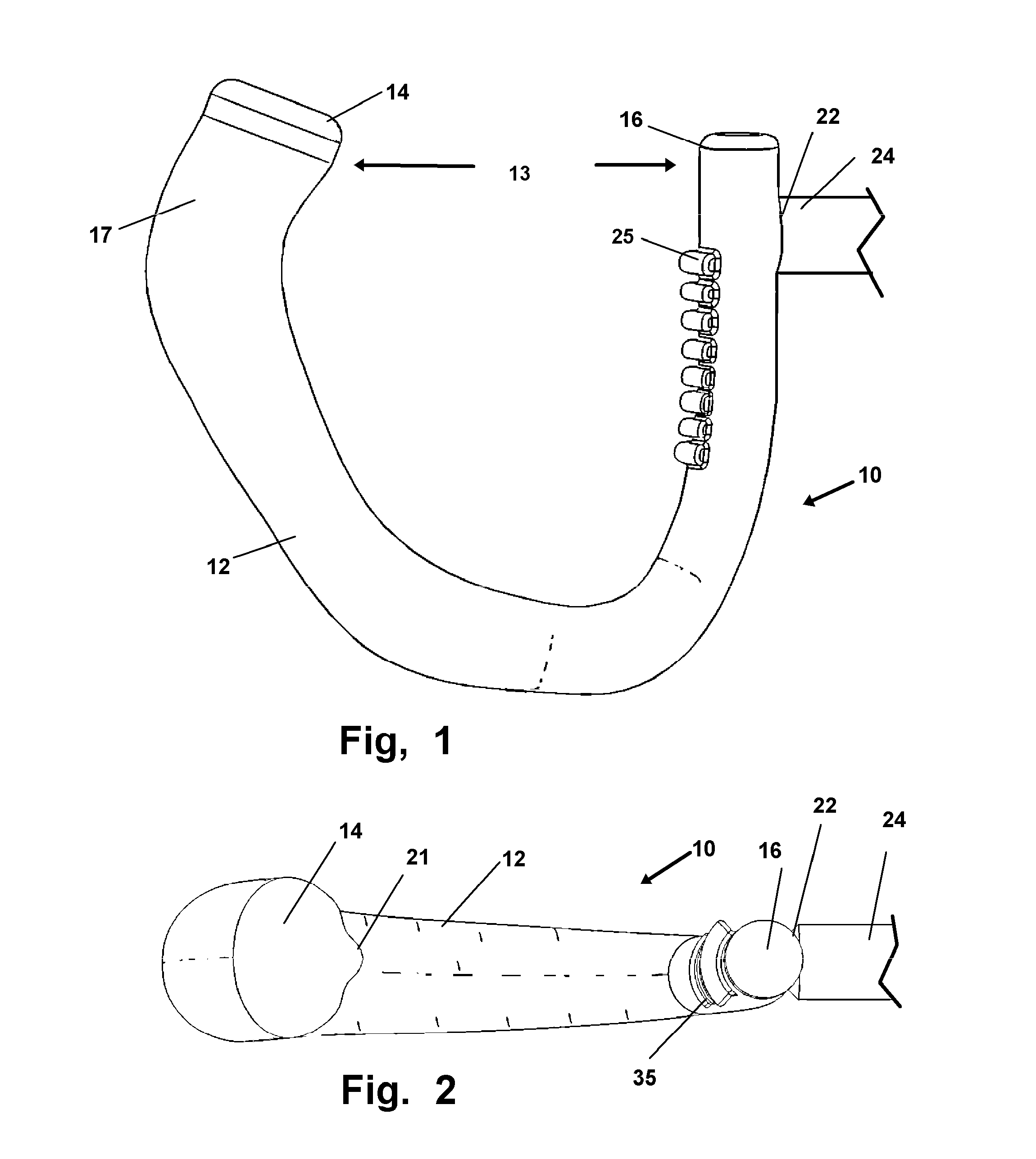
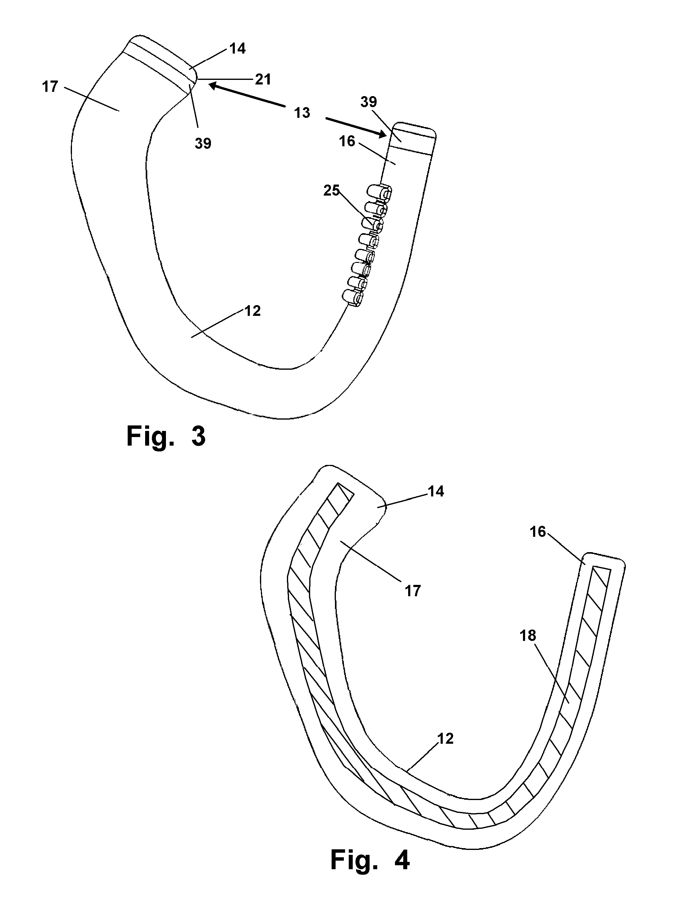
[0067]Referring now to the drawings of FIGS. 1-18 showing the sexual aid device 10 in various preferred modes, wherein similar parts are identified by like reference numerals which may be found in one or more of the drawings.

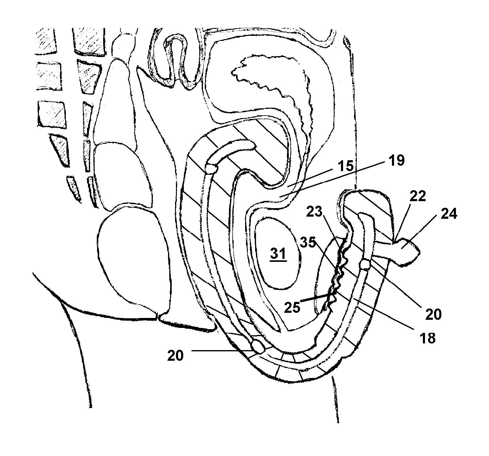
[0068]As shown in figures the device 10, is configured to provide a self-retained biased engagement of the device 10 with a female wearer, as shown in FIG. 9, without the aid of belts or straps but instead using a clamping action provided by a force of the ends of the device toward each other.

[0069]So employed, the device 10 has a generally U-shaped member 12 having a first or proximal end 14 which is adapted for a biased contact in an intra vaginal engagement with the wearer through a hooked portion 17 formed by a bend adjacent to the proximal end 14 of the U-shaped member 12. A projection 21 at the proximal end 14 provides increased force and friction with the G-spot area 19 of the female user as shown in FIG. 9, is preferred to increase sexual stimulation and...


PUM


Abstract

A sexual aid device formed of a substantially U-shaped, member having a proximal end adapted for engagement within the vagina of a user distal end positioned to oppose the proximal end in a biased engagement with intra vaginal and external sexually sensitive surfaces of the user's body. A skeletal member running axially within said U-shaped member may be employed to vary the force of the biased engagement and reshape the U-shaped member. A projecting elongated member adjacent to the distal end of the U-shaped member is engageable by the user or body contact with a second user to impart force to the U-shaped member for sexual stimulation.

Description

[0001]This application is a Continuation-in-Part of U.S. Non-Provisional patent application Ser. No. 12 / 564,013 filed on Sep. 21, 2009, which claims priority to Provisional Patent Application No. 61 / 098,572 filed on Sep. 19, 2008, both of which are incorporated herein in their respective entirety by reference.BACKGROUND OF THE INVENTION[0002]1. Field of the Invention[0003]The present invention relates to articles which are adapted to enhance sexual function and user pleasure. More specifically, the device relates to a sexual stimulation device which is retainable upon the female wearer without the aid of straps and belts and which may be adapted for concurrent use between two sexual partners or simply employed by a single user. The device is dimensioned in a manner to sexually stimulate intra vaginal and external erotic arousal areas of users. The device is further configured with means for removable engagement of at least one additional sexual stimulation component for employment o...

Claims


Application Information

Patent Timeline
Patent Type & Authority Applications(United States)
IPC IPC(8): A61H19/00
CPCA61H19/44A61H19/34A61H19/50A61H23/02A61H2201/165A61H2201/1685
Inventor DE ALVA, JOHN
Owner DE ALVA JOHN
Why Eureka
Try Eureka