
Door lock assembly for a dwelling

a door lock and housing technology, applied in the field of door lock assemblies for dwellings, can solve the problems of ineffective sealing, insufficient sealing between the door panel and the frame, and the locking mechanism itself does not function as sealing elements,

Active Publication Date: 2014-08-28
OTTO LLC +1
View PDF11 Cites 54 Cited by
  • Summary
  • Abstract
  • Description
  • Claims
  • Application Information

AI Technical Summary

Benefits of technology

The coupler element is designed with a narrower middle section and skirted ends. The first end of the drive element has a narrower boss portion and a connection element, while the first end of the coupler element has a cut-out to receive the boss portion. The boss portion is securely attached to the first end of the drive element using a recess. This design ensures proper connection and stability between the coupler element and the drive element.

Problems solved by technology

A disadvantage of traditional door entry systems of this type are that they have a single or at most dual point of locking connection between the door panel and the frame.
However, the locking mechanisms themselves do not function as sealing elements, and there is typically an issue associated with these types of door panel seals.
In many instances, the seals are not effective at preventing the transfer of environmental elements such as noise, weather, water, and insects from one side of the panel to the other side.
In many instances, however, this weather stripping fails to act as a sufficient seal between the door panel and the frame.
Another prevalent issue associated with seals formed between the door frame and the door panel or between adjacent panels is that these seals can become disjoined.
Either intentionally or unintentionally, the alignment between the frame and the panel or between adjacent panels may be disturbed which can degrade the quality of the seal, since, in many instances, the integrity of the seal relies upon these members having certain positional relationships relative to one another.

Method used


Image

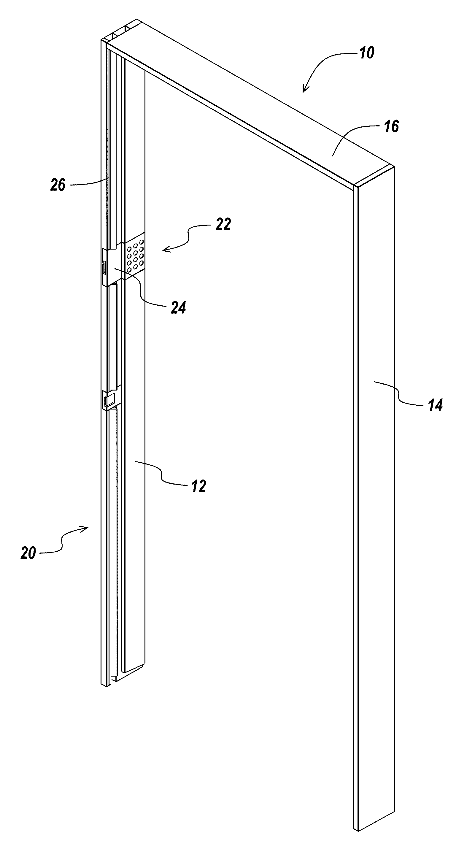
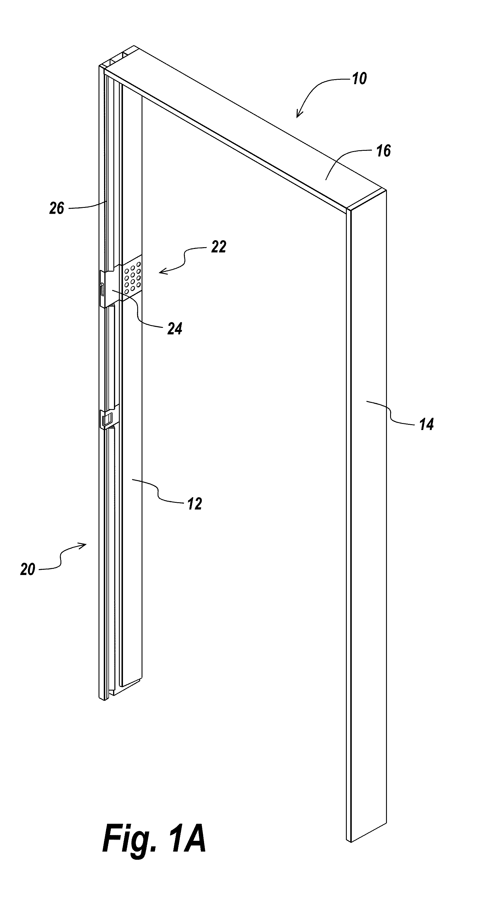
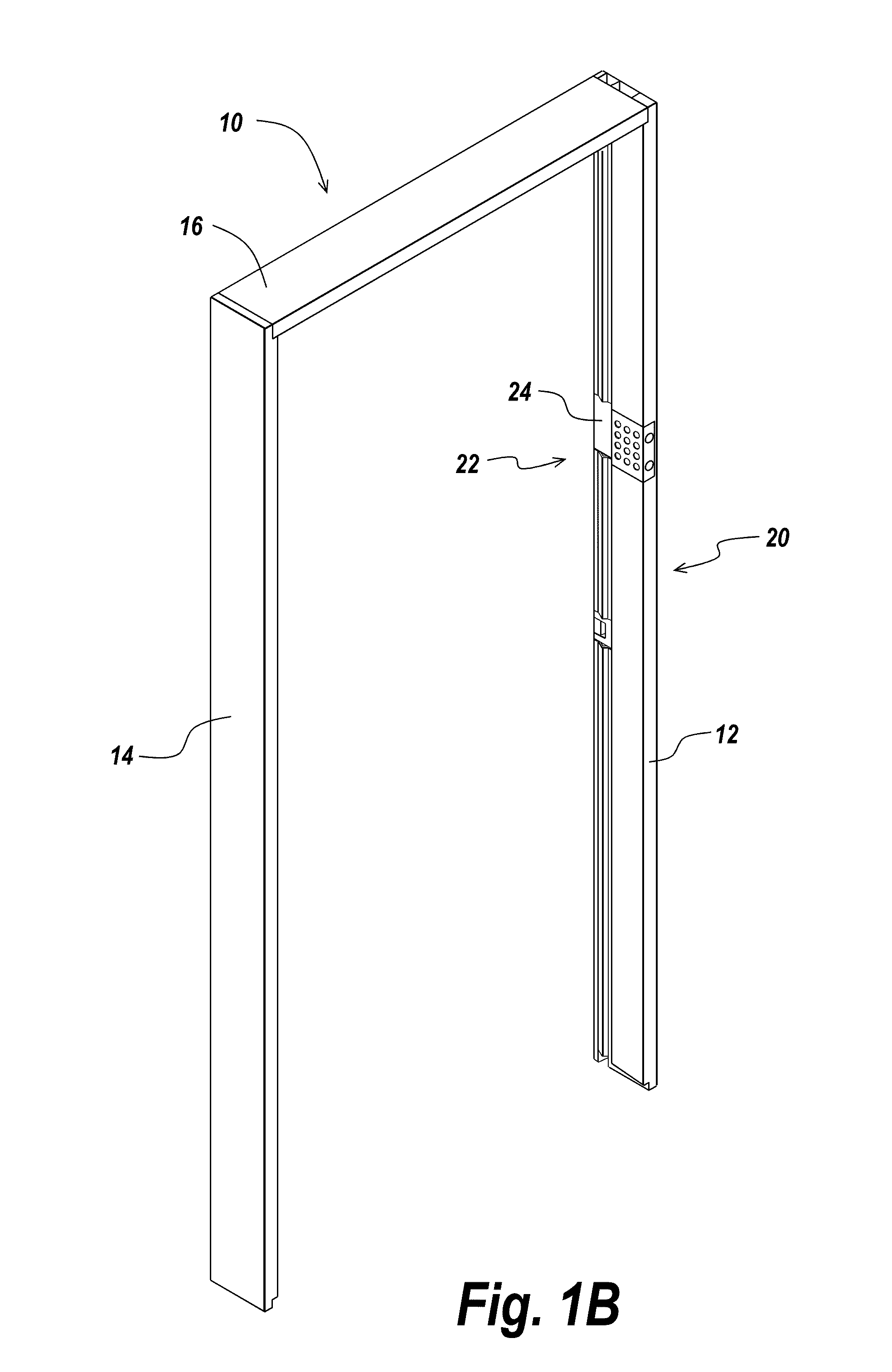
  • Door lock assembly for a dwelling
  • Door lock assembly for a dwelling
  • Door lock assembly for a dwelling

Examples


Embodiment Construction

[0067]The present invention is directed towards a frame based door lock assembly or system that can lock, seal and secure an entrance to a dwelling. The door lock assembly of the present invention is formed and mounted within a door frame and has a movable locking element that, when deployed, locks and seals the door to the frame. As used herein, the term “dwelling” is intended to include any partially or fully enclosed space that requires a door, such as a residential or commercial structure. Examples of dwellings contemplated by the present invention include houses.

[0068]The present invention is also directed towards a door panel based door lock assembly or system that can also lock, seal and secure an entrance to a dwelling. The door lock assembly of the present invention is formed and mounted within a door panel and has a movable locking element that, when deployed, locks and seals the door to the frame.

[0069]The present invention is also directed towards a system and method for...


PUM


Abstract

A door lock assembly for use with a door having a frame element that includes a main body and a pair of opposed sides that forms a channel therebetween. One of the sides of the main body has a connector portion. The assembly also includes a movable locking assembly that is coupled to the connector portion of the frame element and has one or more elongated locking elements that is movable between a locked position and an unlocked position. The assembly also includes a latch assembly configured for coupling a door to a door frame, and if desired an actuator assembly.

Description

RELATED APPLICATIONS[0001]This application claims priority to U.S. Provisional Patent Application No. 61 / 770,605, filed on Feb. 28, 2013 and entitled “FRAME BASED DOOR LOCK FOR DWELLING.” The contents of the aforementioned patent application are incorporated herein by reference.BACKGROUND OF THE INVENTION[0002]Traditional entryways into a dwelling are typically contain an entry door system. The entry door allows ingress and egress to the dwelling. A typical entry door system includes a door frame that includes a plurality of hinge mechanisms that pivotably mount a door panel. The door panel typically includes a handle that has a latch mechanism that cooperates with a strike plate mounted in the frame to hold the door in a closed position. One or more locks can be provided to secure or lock the door in the close position. These conventional locks typically include a handle based or mounted lock that locks or secures the latch in the deployed position, thus locking the door relative t...

Claims


Application Information

Patent Timeline
IPC IPC(8): E05C3/12E05B63/00
CPCE05B63/0052E05C3/12E05C19/002Y10T292/1016E05C9/10G07C9/00571E05B57/00Y10T292/096
Inventor JADALLAH, SAMIRMARTIN, JOHN HILLERICHMARSH, ROBBY A.LYLYK, NICOLAS PEDRO
Owner OTTO LLC
Learn More