Mechanical structure of articulated sheath

a technology of articulation and sheath, applied in the field of medical devices, can solve the problems of lack of dexterity and sensitivity offered to health professionals (endoscopists and surgeons) who perform endoscopic procedures, and the inability of surgeons or endoscopists to easily maneuver endoscopic tools and instruments

Active Publication Date: 2014-08-28
CANON USA +1
View PDF1 Cites 41 Cited by
  • Summary
  • Abstract
  • Description
  • Claims
  • Application Information

AI Technical Summary

Problems solved by technology

However, one of the major shortcomings in the current state of the art of endoscopic tools is the lack of dexterity and sensitivity offered to health professionals (endoscopists and surgeons) who perform endoscopic procedures.
In particular, many conventional endoscopic instruments with rigid or flexible sheaths prevent the surgeon or endoscopist from easily maneuvering endoscopic tools and instruments due to the rigidity of the mechanical structure of the sheath.
More importantly, rigid or flexible sheaths prevent the surgeon from obtaining an accurate feeling (feedback feeling) of the amount of pressure or force exerted by an end effector on the organ or tissue u

Method used


Image

  • Mechanical structure of articulated sheath
  • Mechanical structure of articulated sheath
  • Mechanical structure of articulated sheath

Examples


first embodiment

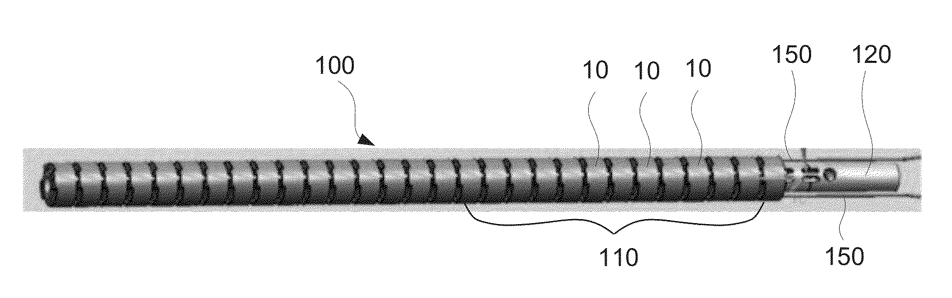
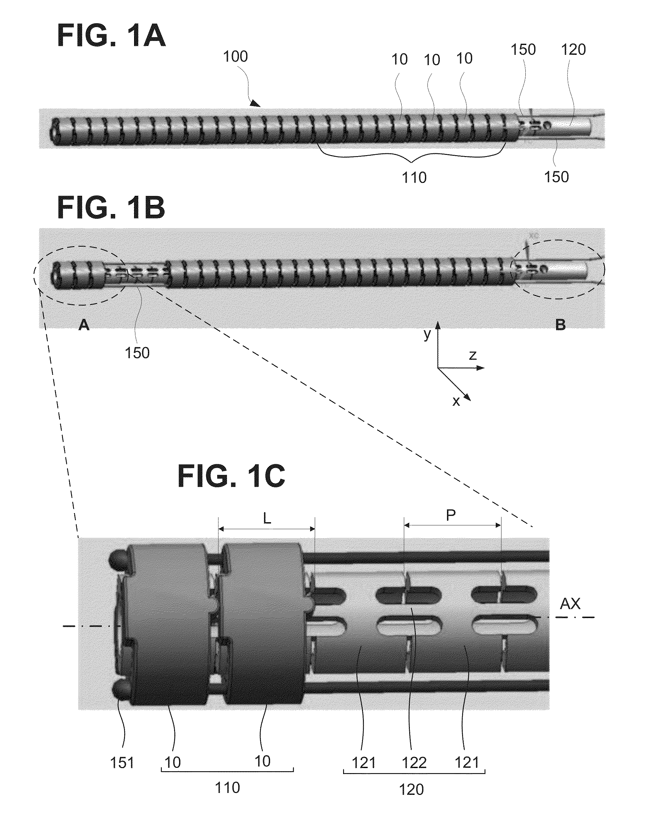
[0049]FIGS. 1A through 1C illustrate an exemplary configuration of a basic mechanical structure of an articulated sheath100, in accordance with an embodiment of the present invention. As used herein, the term “basic mechanical structure” refers to a basic building block or smallest unit or sheath section of the articulated sheath 100 necessary to obtain a minimal articulation (bend) along an angle of plus / minus theta (θ) with respect to a central axis (linear axis) AX of the articulated sheath 100. As illustrated in FIG. 1A, an articulated sheath 100 includes an outer body 110 made of a plurality of node rings 10, and inner body 120 arranged inside the outer body 110, and a plurality of wires 150 passing through holes in the plurality of node rings 10.

[0050]As illustrated in FIG. 1B, the plurality of node rings 10 of the outer body 110 are stacked or arranged in series one upon another; and the wires 150 pass through holes formed in the wall of each node ring 10. In this manner, the...

numerical examples

[0087]

R=1 mm, m=0.3,

When (T / dT)=1, ε≦0.333 mm,

When (T / dT)=2, ε≦0.167 mm,

When (T / dT)=5, ε≦0.067 mm,

When (T / dT)=10, ε≦0.033 mm,

[0088]The sample values above show that smaller (T / dT) tolerates larger offset displacement ε. In other words, it is more desirable for the balancing tension of T to be as small as possible. On the other hand, in a case where an uncontrolled outside force is exerted, it is desirable to maintain the balancing tension T to be a large value to resist the outside force.

[0089]In order to bend the whole structure of sheath 100 to a small radius, the ratio T / dT is small (e.g., 2). On the other hand, in order to slightly bend the structure of sheath 100 to a large radius of curvature, the ratio T / dT is large (e.g., 10). It was observed that in order to maintain the stability of the mechanical structure under various error factors and outside forces, (T / dT) is greater or equal to 2. Thus, to maintain an stable control of sheath 100 with the efficiency of η≧90%, the fol...


PUM


Abstract

A sheath apparatus includes, a plurality of node rings configured to be tilted with respect to each other, each node ring defining a substantially cylindrical wall and having at least one hole passing through said cylindrical wall, the plurality of node rings being arranged next to each other along a linear axis such that consecutive node rings contact each other at a contact plane; a manipulating wire going through the holes in said stacked node rings; and a position restoring component configured to restore said stacked node rings from a tilted position to an original position, wherein said position restoring component is located inside or outside of the stacked node rings.

Description

CROSS-REFERENCE TO RELATED APPLICATIONS[0001]This application claims priority from Provisional Application No. 61 / 770,883 filed 28 Feb. 2013, the disclosure of which is hereby incorporated by reference herein in its entirety.BACKGROUND[0002]1. Field[0003]The disclosure of this application relates generally to medical devices and in particular to an articulated sheath applicable to remote robotic manipulation of surgical tools and instruments, such as endoscopes.[0004]2. Related Art[0005]Endoscopic surgical instruments and tools are well known and continue to gain acceptance in the medical field. An endoscopic instrument or tool generally includes a rigid or flexible tube commonly referred to as a sleeve or sheath. One or more channels extend along (typically inside) the sheath to allow access to end effectors located at a distal end of the sheath. Control mechanisms located at a proximal end of the sheath are configured to enable remote manipulation of the end effectors via the one ...

Claims


Application Information

Patent Timeline
IPC IPC(8): A61B1/018A61B1/008A61B1/04
CPCA61B1/018A61B1/04A61B1/008A61B1/0055A61B1/0016A61B1/0057A61B17/00234A61B2017/00309A61B2017/00314A61B2017/00327A61M25/0147
Inventor KATO, TAKAHISAOKUMURA, ICHIROHATA, NOBUHIKO
Owner CANON USA
Why Eureka
Try Eureka