Segmentally structured disk triboelectric nanogenerator

Active Publication Date: 2014-09-04
GEORGIA TECH RES CORP
View PDF3 Cites 76 Cited by
  • Summary
  • Abstract
  • Description
  • Claims
  • Application Information

AI Technical Summary

Problems solved by technology

The sliding mechanism is configured to move the first member laterally against the second member in a first direction, thereby generating an electric potential imbalance between the first electrode and the second electrode.
The first member is slid laterall

Method used


Image

  • Segmentally structured disk triboelectric nanogenerator
  • Segmentally structured disk triboelectric nanogenerator
  • Segmentally structured disk triboelectric nanogenerator

Examples


Embodiment Construction

[0037]A preferred embodiment of the invention is now described in detail. Referring to the drawings, like numbers indicate like parts throughout the views. Unless otherwise specifically indicated in the disclosure that follows, the drawings are not necessarily drawn to scale. As used in the description herein and throughout the claims, the following terms take the meanings explicitly associated herein, unless the context clearly dictates otherwise: the meaning of “a,”“an,” and “the” includes plural reference, the meaning of “in” includes “in” and “on.”

[0038]Related U.S. patent application Ser. No. 13 / 598,132, filed on Aug. 29, 2012 by Wang et al. and Ser. No. 14 / 032,864, filed on Sep. 20, 2013 by Wang et al. disclose methods of making triboelectric generators and components thereof and are both incorporated herein by reference for the purpose of disclosing such methods.

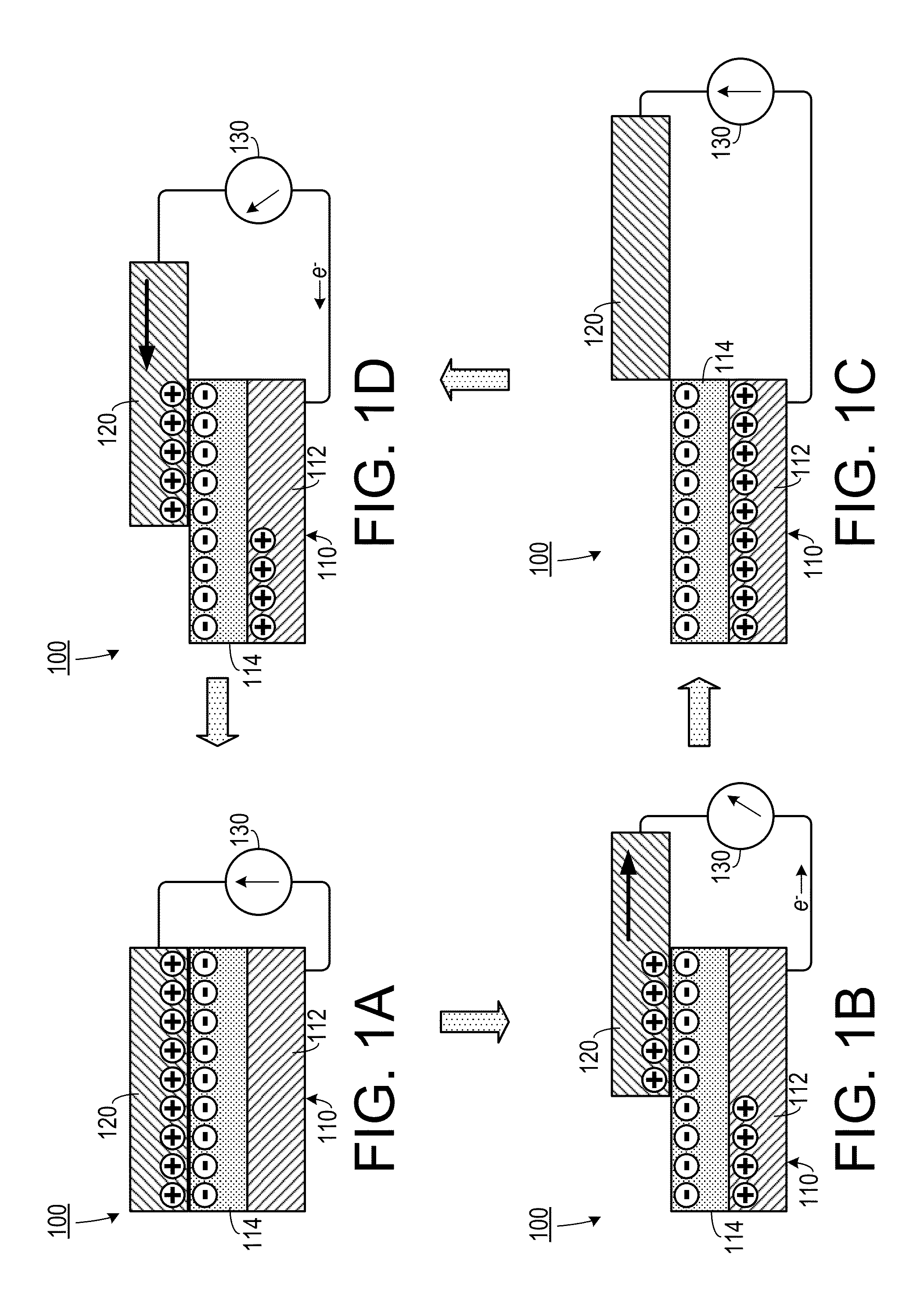
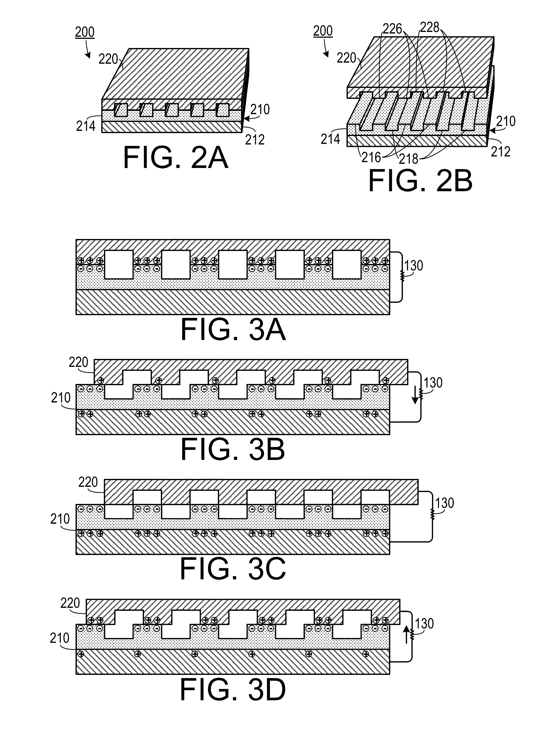
[0039]The present invention includes a triboelectric nanogenerator (TENG) that converts small-scale mechanical ener...


PUM


Abstract

A generator includes a disc shaped first unit, a disc shaped second unit and an axle. The first unit includes a substrate layer, a double complementary electrode layer and an electrification material layer. The electrode layer includes a first electrode member and a second electrode member. The first electrode member includes evenly spaced apart first electrode legs extending inwardly. The second electrode member is complementary in shape to the first electrode member. The legs of the first electrode member and the second electrode member are interleaved with each other and define a continuous gap therebetween. The electrification material includes a first material that is in a first position on the triboelectric series. The second unit defines elongated openings and corresponding elongated leg portions, and includes a second material that is at a second position on a triboelectric series, different than the first position.

Description

CROSS-REFERENCE TO RELATED APPLICATION(S)[0001]This application claims the benefit of the following: U.S. Provisional Patent Application Ser. No. 61 / 814,373, filed on Apr. 22, 2013, U.S. Provisional Patent Application Ser. No. 61 / 945,409, filed on Feb. 27, 2014, U.S. Provisional Patent Application Ser. No. 61 / 845,618, filed on Jul. 12, 2013, U.S. Provisional Patent Application Ser. No. 61 / 827,901, filed on May 28, 2013, the entirety of each of which is hereby incorporated herein by reference.[0002]This application is a continuation-in-part of, and claims the benefit of, U.S. patent application Ser. No. 14 / 189,656, filed on Feb. 25, 2014, which claims priority on U.S. Provisional Application Ser. No. 61 / 771, 371, filed on Mar. 1, 2013, the entirety of which is hereby incorporated herein by reference.STATEMENT OF GOVERNMENT INTEREST[0003]This invention was made with government support under agreement No. DE-FG02-07ER46394, awarded by the Department of Energy. The government has certai...

Claims


Application Information

Patent Timeline
IPC IPC(8): H02N1/04
CPCH02N1/04
Inventor WANG, ZHONG LINZHU, GUANGLIN, LONGWANG, SIHONGCHEN, JUN
Owner GEORGIA TECH RES CORP
Why Eureka
Try Eureka