Low-noise signal amplifying circuit and method thereof

a low-noise signal and amplifier technology, applied in the direction of low-noise amplifiers, amplifiers with semiconductor devices only, amplifiers with semiconductor devices/discharge tubes, etc., can solve the problems of considerable challenge in lna design, and achieve low noise-figures and low return loss

Active Publication Date: 2014-09-11
RAFAEL MICROELECTRONICS INC
View PDF5 Cites 1 Cited by
  • Summary
  • Abstract
  • Description
  • Claims
  • Application Information

AI Technical Summary

Benefits of technology

[0005]One of the objectives of the present invention is to provide a low-noise amplifier having low noise-figure and low return loss and the related method.

Problems solved by technology

Accordingly, the LNA design presents considerable challenge due to its simultaneous requirement for high gain, low noise figure, good input and output matching and unconditional stability at the lowest possible current draw from the LNA.

Method used


Image

  • Low-noise signal amplifying circuit and method thereof
  • Low-noise signal amplifying circuit and method thereof
  • Low-noise signal amplifying circuit and method thereof

Examples


Embodiment Construction

[0015]Certain terms are used throughout the description and following claims to refer to particular components. As one skilled in the art will appreciate, electronic equipment manufacturers may refer to a component by different names. This document does not intend to distinguish between components that differ in name but not function. In the following description and in the claims, the terms “include” and “comprise” are used in an open-ended fashion, and thus should be interpreted to mean “include, but not limited to . . . ”. Also, the term “couple” is intended to mean either an indirect or direct electrical connection. Accordingly, if one device is coupled to another device, that connection may be through a direct electrical connection, or through an indirect electrical connection via other devices and connections.

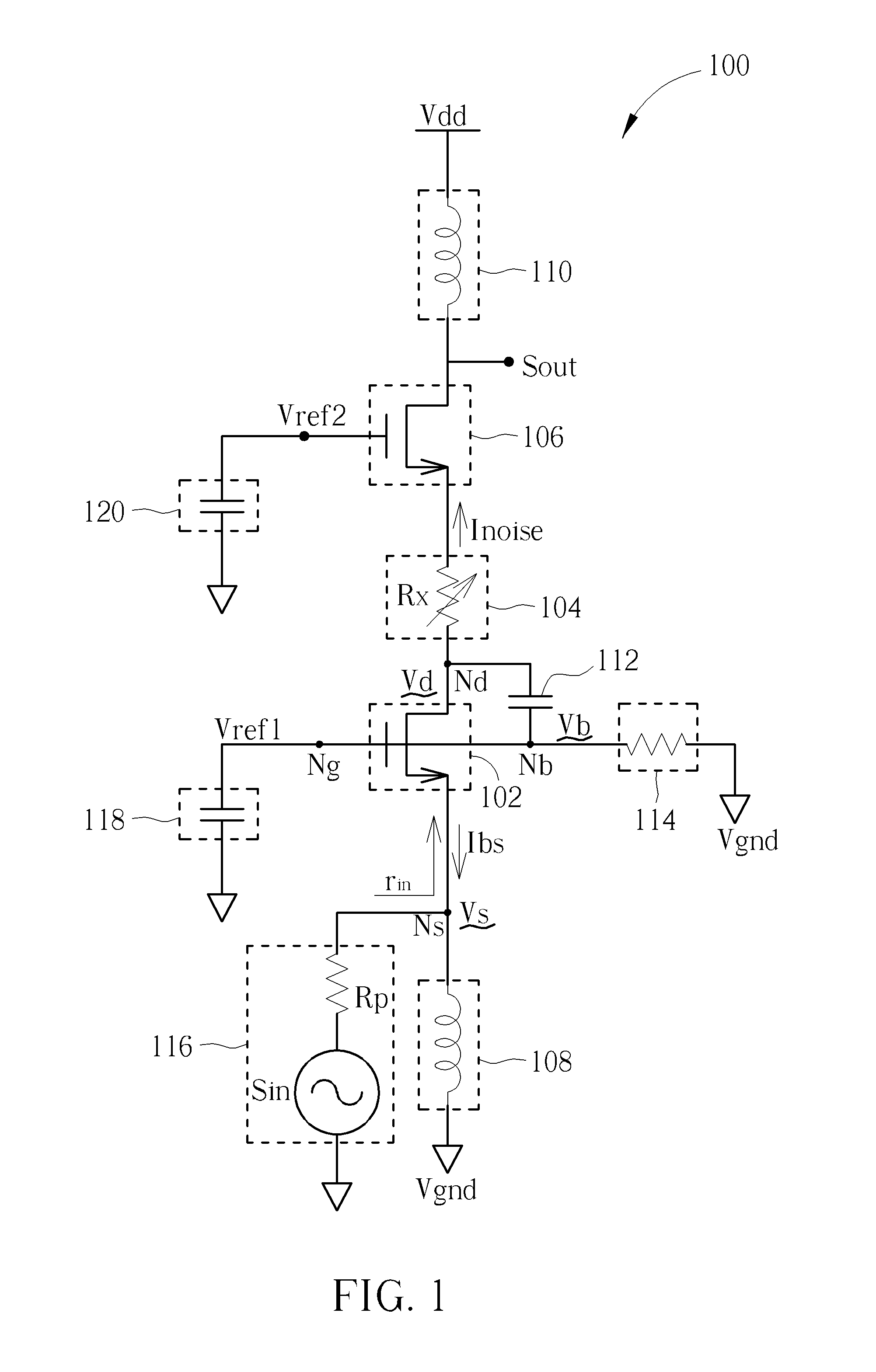
[0016]Please refer to FIG. 1, which is a diagram illustrating a signal amplifying circuit 100 according to an embodiment of the present invention. The signal amplifying c...


PUM


Abstract

A signal amplifying circuit includes: a first transistor having a first connecting terminal coupled to an input signal, and a controlling terminal coupled to a first reference voltage; an adjustable resistive circuit having a first terminal coupled to a second connecting terminal of the first transistor; and a second transistor having a first connecting terminal coupled to a second terminal of the adjustable resistive circuit, a controlling terminal coupled to a second reference voltage, and a second connecting terminal for outputting an output signal corresponding to the input signal; wherein a resistance of the adjustable resistive circuit is adjusted to make an input impedance looking into the first transistor from the first connecting terminal equal a predetermined impedance.

Description

BACKGROUND OF THE INVENTION[0001]1. Field of the Invention[0002]The present invention relates to a low-noise signal amplifying circuit and method thereof, and more particularly to a low-noise amplifier having low noise-figure and low return loss and the related method.[0003]2. Description of the Prior Art[0004]In a wireless communication system, the LNA provides the first level of amplification of the RF signal received at the system's antenna. Therefore, the main function of the LNA is to amplify the extremely low RF signals without adding noise, thus preserving the required signal-to-noise ratio (SNR) of the system at extremely low power levels. Moreover, when the LNA is arranged to receive the RF signal, the impedances between the input terminal of the LNA and the previous circuit stage should be matched to reduce the return loss of the RF signal. Accordingly, the LNA design presents considerable challenge due to its simultaneous requirement for high gain, low noise figure, good ...

Claims


Application Information

Patent Timeline
Patent Type & Authority Applications(United States)
IPC IPC(8): H03F3/193
CPCH03F3/193H03F1/223H03F2200/294
Inventor KAN, MENG-PING
Owner RAFAEL MICROELECTRONICS INC
Why Eureka
Try Eureka