3 Band Tv-Rf Input Circuit

a tv-rf input circuit and input circuit technology, applied in continuous tuning, discontnuous tuning with seperate pre-tuned circuits, television systems, etc., can solve the problems of large tuning/matching coils, expected to present broadband antenna problems, and difficult miniaturization, etc., to achieve low noise figures

Inactive Publication Date: 2008-02-07
NXP BV
View PDF6 Cites 0 Cited by
  • Summary
  • Abstract
  • Description
  • Claims
  • Application Information

AI Technical Summary

Benefits of technology

[0008] It is, accordingly, an object of the present invention to provide a tuner input circuitry for receiving RF signals with a low noise figure.

Problems solved by technology

However and in particular for off-air and mobile applications both digital and analog, many issues have to be addressed.
These transmitters are expected to present problems for the broadband antenna, be it mobile or fixed until it is finally turned off, if ever.
The TV-RF input circuit of U.S. Pat. No. 4,851,796 has the following drawbacks: no CB trap in any band, no FM trap, a high noise figure for UHF (requirement for FNAC are S / N 47 dB typical) and in low band (in particular at the edges) due to large coupling / matching coils used, large tuning / matching coils make miniaturization difficult (apart from this, the coil must be mechanically secured to prevent micro-phony and it also has a self resonance that causes problems in high band) and surge protection not sufficiently high.

Method used


Image

  • 3 Band Tv-Rf Input Circuit
  • 3 Band Tv-Rf Input Circuit
  • 3 Band Tv-Rf Input Circuit

Examples


Embodiment Construction

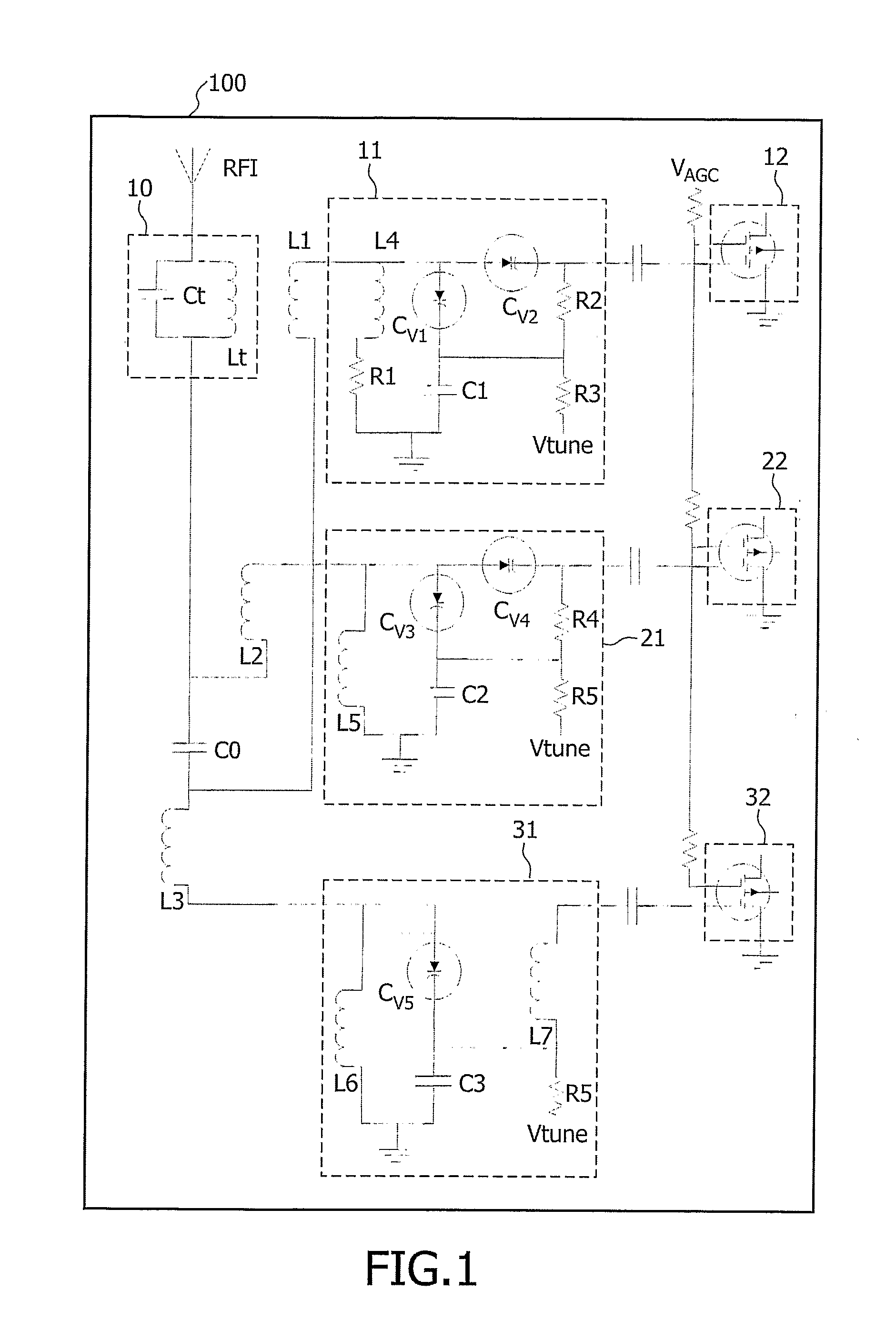
[0020]FIG. 1 shows a prior art RF input circuit 100. The (TV−) RF input circuit 100 comprises an IF trap filter 10 for suppressing signals at the TV image and sound intermediate frequency, via which the RF aerial input RFI is coupled to an input of a high-pass .pi.-section C, L2, L3. The .pi.-section C, L2, L3 comprises in a .pi.-configuration a capacitor C arranged in a capacitive series branch one end of which is connected to the input end of the .pi.-section and is coupled to a first inductive shunt branch and the other end of which is connected to the output end of the .pi.-section and is coupled to a second inductive shunt branch. The output of the .pi.-section is coupled to a first RF resonant circuit 11 via a coupling coil L1 functioning as a so-called first series inductance. The first and second inductive shunt branches are constituted by coupling coils L2 and L3, respectively functioning as so-called second and third series inductances. These first, second and third signal...


PUM


Abstract

The present invention relates to a TV-tuner input circuit. The input circuit comprises an RF coupling device via which RF an aerial input (RFI) is coupled to first (330), second (340) and third (350) parallel tunable RF resonant circuits for a parallel selection of a desired frequency in first, second and third TV frequency bands substantially succeeding one another in frequency. The first RF resonant circuit comprises a first RF resonance circuit inductance (L6) and wherein said RF coupling device having a first series inductance (L3) that can be magnetically coupled with the first RF resonance circuit inductance (L6) enabled by a switched capacitor (Cu) using a band-high switch (Vhigh). In one embodiment the third RF resonant circuit includes a tuned ½ RF trap (320). In another embodiment the RF coupling device further comprises an FM trap (380), and wherein the FM trap (380) can be bypassed by switching a capacitor (Cinf1) by using an FM-switch (Vfm).

Description

FIELD OF THE INVENTION [0001] The invention relates to a TV-RF input circuit provided with an RF coupling device via which an aerial input is coupled to first, second and third parallel tunable RF resonant circuits for a parallel selection of a desired frequency in first, second and third TV frequency bands substantially succeeding one another in frequency, said RF coupling device having a much improved noise figure. [0002] The present invention is particularly relevant for a TV-tuner and TV-Front-end that brings improvements, e.g., to watching broadcasted content on a TV, or, to watching analogue and digitally broadcasted content on a matrix display that is, e.g., part of a mobile gadget etc. BACKGROUND OF THE INVENTION [0003] In a known TV tuner, the first, second and third RF resonant circuits are arranged in first, second and third signal paths, respectively, which are mutually parallel arranged between the coupling device, on the one hand, and a TV-IF output of the tuner on the...

Claims


Application Information

Patent Timeline
Patent Type & Authority Applications(United States)
IPC IPC(8): H04N5/50H01Q5/00H03J3/18H03J3/20H03J5/24H04B1/18
CPCH03J3/185H03J5/244H03J3/20H03J5/24H04N5/50H04B1/18
Inventor KWONG, KAM CHOON
Owner NXP BV
Why Eureka
Try Eureka