
Z-Shaped Bus Bar for a Battery Pack

a battery pack and bus bar technology, applied in the field of battery packs, can solve the problems of small resistance, affecting and reducing the manufacturing cost of battery packs, and reducing the efficiency of air-based or liquid-coolant-based cooling systems

Active Publication Date: 2014-09-11
ATIEVA USA INC
View PDF3 Cites 74 Cited by
  • Summary
  • Abstract
  • Description
  • Claims
  • Application Information

AI Technical Summary

Benefits of technology

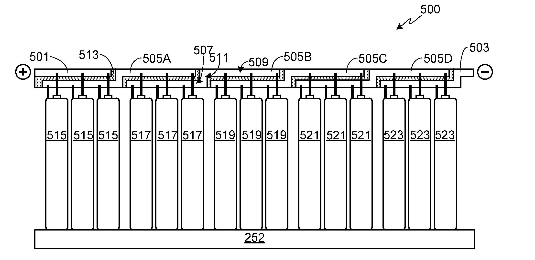
The present invention provides a strong and compact bus bar assembly for use in a battery pack. The battery pack includes multiple batteries that are divided into groups, each containing a subset of batteries that are connected in parallel, and then connected in series. Each battery has two terminals at one end. Bus bars are positioned near the beginning of each battery. Each battery in a group is connected to a bus bar segment of an adjacent bus bar via its terminals. This design ensures a reliable and efficient connection between the batteries in the pack.

Problems solved by technology

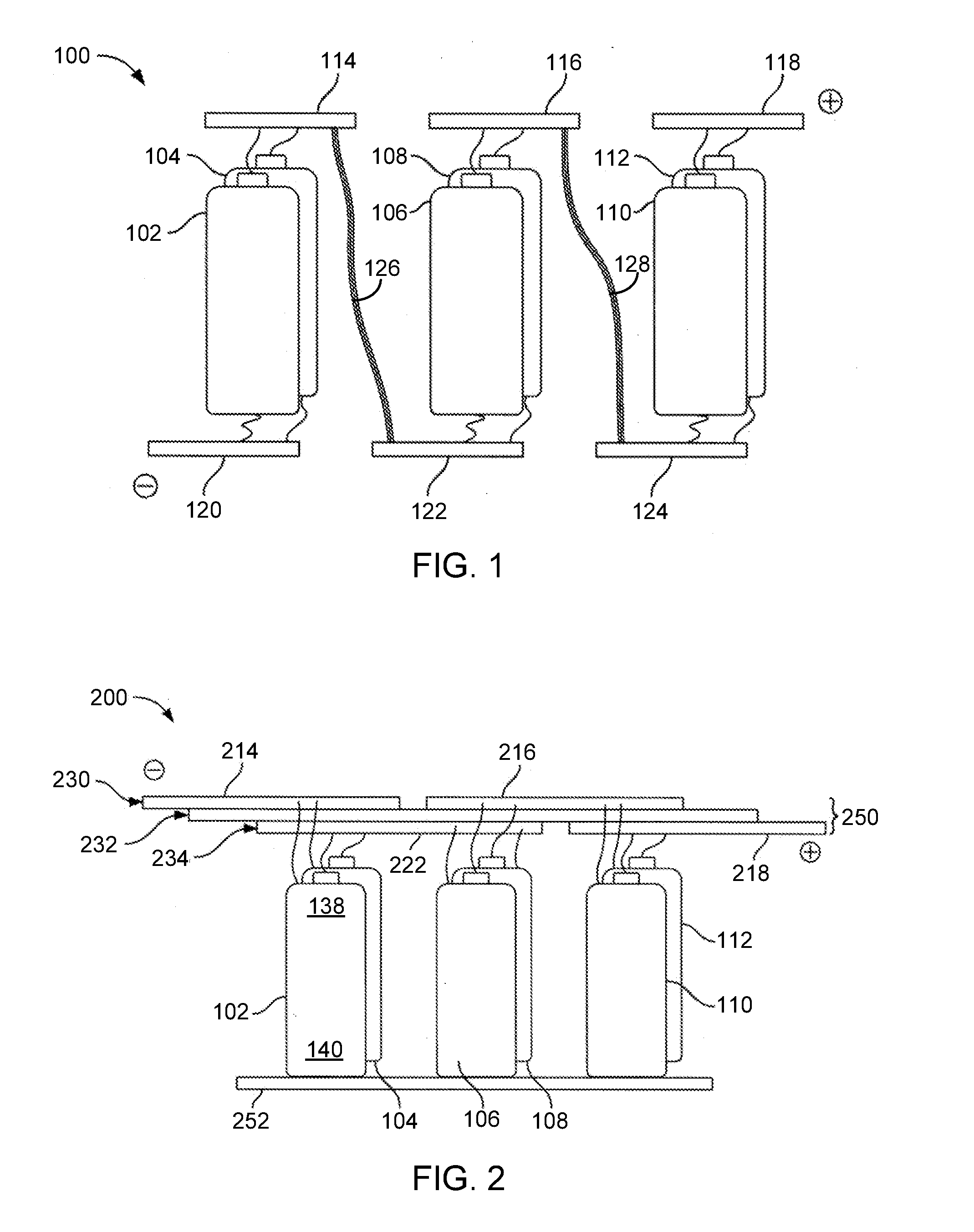
Unfortunately, connections to the bottoms of the cells may prevent the efficient operation of either an air-based or a liquid coolant-based cooling system that is being used to remove the heat generated by the cells during operation.
In addition, the high current interconnect from the bottoms of the cells to the bus bars, which may be in the form of a wire somewhat longer than the length of the cell, introduces a small amount of resistance which gives rise to a voltage drop at high current levels.
Furthermore, assembly of this wire to the bus bars and / or to the bottom of each of the batteries adds to the manufacturing cost of the battery pack while potentially introducing reliability issues.

Method used


Image

  • Z-Shaped Bus Bar for a Battery Pack
  • Z-Shaped Bus Bar for a Battery Pack
  • Z-Shaped Bus Bar for a Battery Pack

Examples


Embodiment Construction

[0026]As used herein, the singular forms “a”, “an” and “the” are intended to include the plural forms as well, unless the context clearly indicates otherwise. The terms “comprises”, “comprising”, “includes”, and / or “including”, as used herein, specify the presence of stated features, integers, steps, operations, elements, and / or components, but do not preclude the presence or addition of one or more other features, integers, steps, operations, elements, components, and / or groups thereof. As used herein, the term “and / or” and the symbol “ / ” are meant to include any and all combinations of one or more of the associated listed items. Additionally, while the terms first, second, etc. may be used herein to describe various steps or calculations, these steps or calculations should not be limited by these terms, rather these terms are only used to distinguish one step or calculation from another. For example, a first calculation could be termed a second calculation, and, similarly, a first...


PUM

PropertyMeasurementUnit
electrically insulatingaaaaaaaaaa
resistanceaaaaaaaaaa
lengthaaaaaaaaaa

Abstract

A battery pack with a compact and robust bus bar assembly is provided. The batteries within the pack are divided into groups, where the batteries within each battery group are connected in parallel and the groups are connected in series. A repetitive sequence of overlapping bus bars is used, with each bus bar comprised of upper and lower segments coupled together via a step segment. The overlapping design allows the upper surface of the upper segment of each of the repetitive bus bars to be aligned within an upper plane, and the lower surface of the lower segment of each of the repetitive bus bars to be aligned within a lower plane.

Description

CROSS-REFERENCE TO RELATED APPLICATION[0001]This application is a continuation-in-part of U.S. patent application Ser. No. 13 / 794,535, filed 11 Mar. 2013, the disclosure of which is incorporated herein by reference for any and all purposes.FIELD OF THE INVENTION[0002]The present invention relates generally to battery packs and, more particularly, to a robust and compact design for a battery pack bus bar.BACKGROUND OF THE INVENTION[0003]A bus bar is a metal strip or bar that conducts electricity and is used for electrical power distribution. Battery cells can be connected with bus bars to make battery packs. Some battery packs using cylindrical cells make electrical connections to the tops and the bottoms of the cells. When connecting cells in series, bus bars and high current interconnects link the positive terminal of one cell, or a parallel group of cells, to the negative terminal of the next cell or the next parallel group of cells. Unfortunately, connections to the bottoms of th...

Claims


Application Information

Patent Timeline
Patent Type & Authority Applications(United States)
IPC IPC(8): H01M2/20H01M50/213H01M50/296H01M50/503H01M50/507H01M50/516
CPCH01M2/206H01M10/643H01M10/655H01M10/613Y02E60/10H01M50/507H01M50/213H01M50/516H01M50/296H01M50/503
Inventor JAN, JAMESBISKUP, RICHARD J.TSAI, BENSONRAWLINSON, PETER DORE
Owner ATIEVA USA INC
Learn More