
Display system utilizing vehicle and trailer dynamics

a display system and vehicle technology, applied in the direction of television systems, trailer steering, instruments, etc., can solve the problems of limiting the usefulness of the system, affecting the reversal of the vehicle while towing the trailer, and the trailer departing from a desired path for many drivers

Active Publication Date: 2014-09-18
FORD GLOBAL TECH LLC
View PDF5 Cites 304 Cited by
  • Summary
  • Abstract
  • Description
  • Claims
  • Application Information

AI Technical Summary

Benefits of technology

The present invention relates to a system that helps drivers monitor the angle between their vehicles and trailers. The system includes multiple cameras on the vehicle and trailer that capture images. A controller then selects which camera to display on a screen based on the angle between the vehicles. This allows for a better view of the connection between the vehicles and trailer. The system can also generate an aerial view of the vehicles and trailer based on the angle between them. This invention aims to improve safety and efficiency when driving vehicles and trailers.

Problems solved by technology

Reversing a vehicle while towing a trailer is very challenging for many drivers.
Another reason for such difficulty is that small errors in steering while backing a vehicle with an attached trailer are amplified thereby causing the trailer to depart from a desired path.
Unfortunately most of the real-world use cases of backing a trailer involve a curved path and, thus, assuming a path of zero curvature would significantly limit usefulness of the system.
Undesirably, such implementations of the trailer backup assist systems are known to have a relatively complex human machine interface (HMI) device to specify the path, obstacles and / or goal of the backup maneuver.
These requirements lead to a relatively complex and costly system.
Another reason backing a trailer can prove to be difficult is the need to control the vehicle in a manner that limits the potential for a jackknife condition to occur.
However, in addition to the jackknife condition creating the inconvenient situation where the vehicle must be pulled forward, it can also lead to damage to the vehicle and / or trailer if certain operating conditions of the vehicle relating to its speed, engine torque, acceleration, and the like are not detected and counteracted.
For example, if the vehicle is travelling at a suitably high speed in reverse and / or subjected to a suitably high longitudinal acceleration when the jackknife condition is achieved, the relative movement of the vehicle with respect to the trailer can lead to contact between the vehicle and trailer thereby damaging the trailer and / or the vehicle.

Method used


Image

  • Display system utilizing vehicle and trailer dynamics
  • Display system utilizing vehicle and trailer dynamics
  • Display system utilizing vehicle and trailer dynamics

Examples


Embodiment Construction

[0068]While various aspects of the inventive subject matter are described with reference to a particular illustrative embodiment, the inventive subject matter is not limited to such embodiments, and additional modifications, applications, and embodiments may be implemented without departing from the inventive subject matter. In the figures, like reference numbers will be used to illustrate the same components. Those skilled in the art will recognize that the various components set forth herein may be altered without varying from the scope of the inventive subject matter.

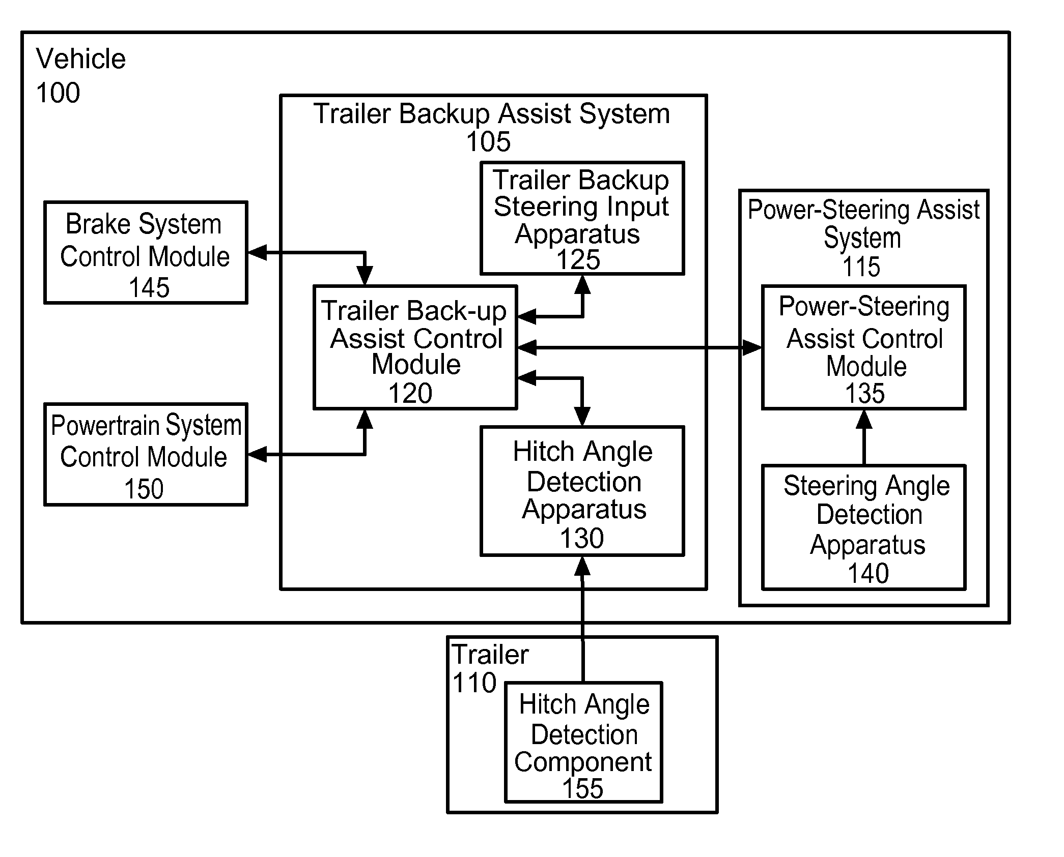
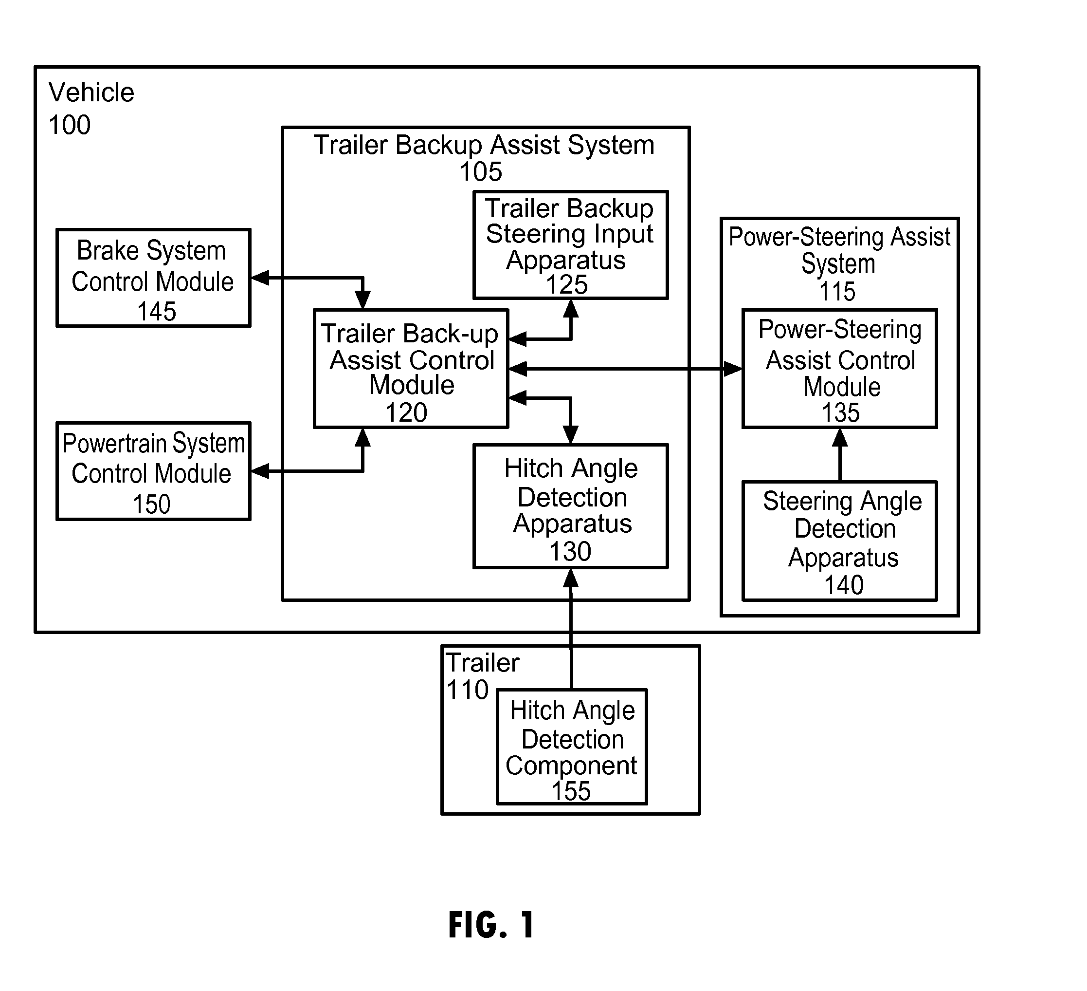
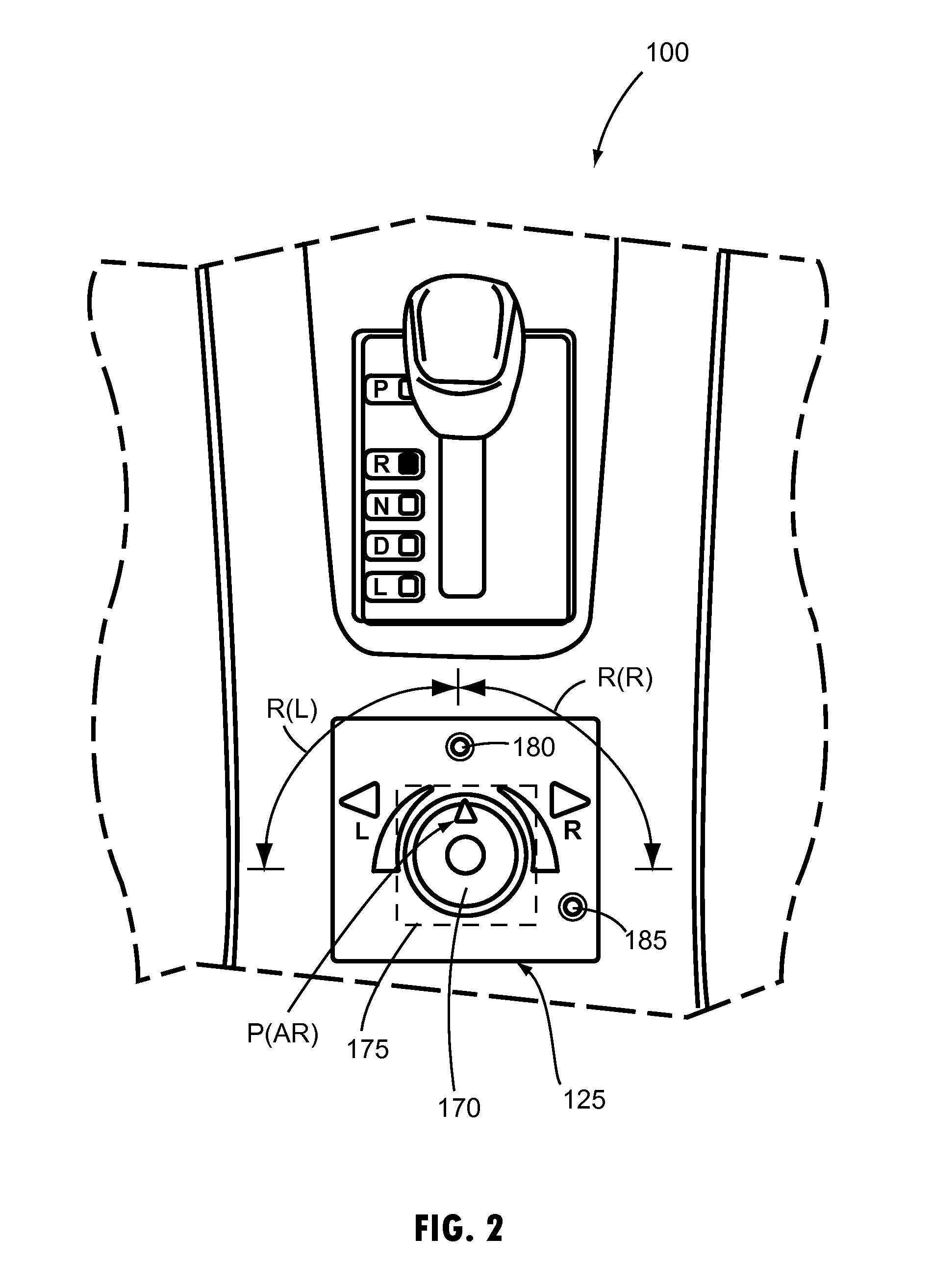
[0069]The disclosed subject matter is directed to providing trailer backup assist functionality in a manner that is relatively low cost and that offers an intuitive user interface. In particular, such trailer backup assist functionality provides for controlling curvature of a path of travel of a trailer attached to a vehicle (i.e., trailer path curvature control) by allowing a driver of the vehicle to specify a desir...


PUM


Abstract

A vehicle and trailer display system is disclosed. The display system includes a plurality of imaging devices disposed on the vehicle, each having a field of view. The display system further includes a screen disposed in the vehicle operable to display images from the imaging devices. A controller is in communication with the imaging devices and the screen and is operable to receive a hitch angle corresponding to the angle between the vehicle and the trailer. Based on the hitch angle, the controller is operable to select a field of view of an imaging device to display on the screen.

Description

CROSS-REFERENCE TO RELATED APPLICATIONS[0001]This patent application is continuation-in-part of U.S. patent application Ser. No. 14 / 256,427, which was filed on Apr. 18, 2014, entitled “CONTROL FOR TRAILER BACKUP ASSIST SYSTEM,” which is a continuation-in-part of U.S. patent application Ser. No. 14 / 249,781, which was filed on Apr. 10, 2014, entitled “SYSTEM AND METHOD FOR CALCULATING A HORIZONTAL CAMERA TO TARGET DISTANCE,” which is a continuation-in-part of U.S. patent application Ser. No. 14 / 188,213, which was filed on Feb. 24, 2014, entitled “SENSOR SYSTEM AND METHOD FOR MONITORING TRAILER HITCH ANGLE,” which is a continuation-in-part of U.S. patent application Ser. No. 13 / 847,508, which was filed on Mar. 20, 2013, entitled “HITCH ANGLE ESTIMATION.” U.S. patent application Ser. No. 14 / 188,213 is also a continuation-in-part of U.S. patent application Ser. No. 14 / 068,387, which was filed on Oct. 31, 2013, entitled “TRAILER MONITORING SYSTEM AND METHOD,” which is a continuation-in-pa...

Claims


Application Information

Patent Timeline
IPC IPC(8): H04N7/18B60R1/00
CPCH04N7/181B60R2300/70B60R2300/808B60R1/003B60D1/245B60D1/62B60W10/04B60W10/18B60W10/20B60W30/02B60W30/18036B60W50/0097B60W50/14B60W2050/143B60W2050/146B60W2300/14B60W2520/22B60W2540/18B60W2540/215B62D13/06B62D15/027B60W30/00G01B7/30G01B11/26H04N7/183
Inventor AICH, SUDIPTOTROMBLEY, ROGER ARNOLDSHUTKO, JOHNMILLER, ALEX MAURICE
Owner FORD GLOBAL TECH LLC
Learn More