Crdm with separate scram latch engagment and locking

Active Publication Date: 2014-09-18
BWXT MPOWER INC +1
View PDF2 Cites 7 Cited by
  • Summary
  • Abstract
  • Description
  • Claims
  • Application Information

AI Technical Summary

Benefits of technology

[0008]In some illustrative embodiments, a control rod drive mechanism (CRDM) comprises: a lead screw engaged by a CRDM motor; a lifting rod supporting at least one control rod; latches secured to the lead screw and configured to latch an upper end of the lifting rod to the lead screw; and a four bar linkage including cam bars, the four bar linkage configured to drive the cam bars inward to cam the latches closed responsive to operation of a latch engagement mechanism; wherein the four bar linkage is configured to bias the latches closed under force of gravity.
[0009]In some illustrative embodiments, a control rod drive mechanism (CRDM) includes: a CRDM motor; an element translated under control of the CRDM motor;
[0010]a latch configured to latch a lifting rod supporting at least one control rod with the element translated under control of the CRDM motor; a latch engagement mechanism configured to close the latch onto the lifting rod; and a latch holding mechanism, separate from the latch engagement mechanism, configured to hold the latch in

Problems solved by technology

In some embodiments the latch engagement mechanism operates responsive to lowering the latches over the upper end of the lifting rod and is not effective to keep the latches closed when the latches are raised again after the latch engagement mechanism operates.
In some embodiments the latch holding mecha

Method used


Image

  • Crdm with separate scram latch engagment and locking
  • Crdm with separate scram latch engagment and locking
  • Crdm with separate scram latch engagment and locking

Examples


Embodiment Construction

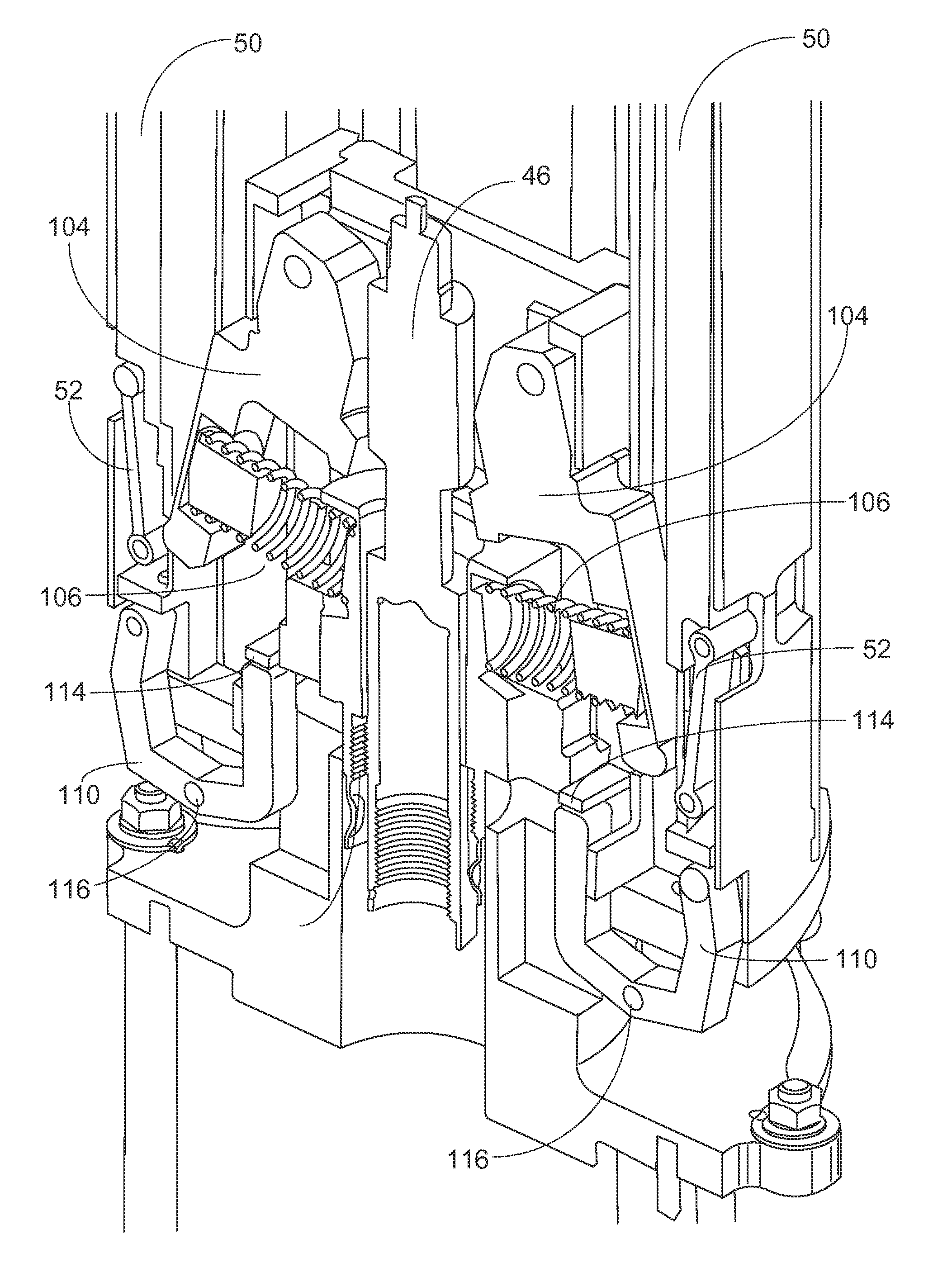
[0026]Disclosed herein are improvements upon CRDM designs of DeSantis et al., U.S. Pub. No. 2011 / 0222640 A1 employing the cam bars with four-bar linkages.

[0027]In one aspect, the CRDM is improved by separating the latch engagement and latch holding functions. This may entail increasing the number of CRDM components since a separate latch engagement mechanism and latch holding mechanism are provided. However, it is recognized herein that this increase in parts is offset by improved energy efficiency. This is because the latch engagement is a momentary event that occurs very infrequently (possibly only once per fuel cycle). In contrast, the latch holding operation is performed over the entire fuel cycle (barring any SCRAM events). By employing separate latch engagement and holding mechanisms, the latch holding mechanism is not required to perform the relatively higher-energy operation of moving the latches from the unlatched position to the latched position. Accordingly, the latch hol...


PUM


Abstract

A control rod drive mechanism (CRDM) configured to latch onto the lifting rod of a control rod assembly and including separate latch engagement and latch holding mechanisms. A CRDM configured to latch onto the lifting rod of a control rod assembly and including a four-bar linkage closing the latch, wherein the four-bar linkage biases the latch closed under force of gravity.

Description

[0001]This application claims the benefit of U.S. Provisional Application No. 61 / 792,235 filed Mar. 15, 2013 and titled “CRDM DESIGNS WITH SEPARATE SCRAM LATCH ENGAGEMENT AND LOCKING”. U.S. Provisional Application No. 61 / 792,235 filed Mar. 15, 2013 and titled “CRDM DESIGNS WITH SEPARATE SCRAM LATCH ENGAGEMENT AND LOCKING” is hereby incorporated by reference in its entirety into the specification of this application.[0002]This application was conceived in the course of work supported by the Department of Energy Cooperative Agreement No. DE-NE0000583. The Department of Energy may have certain rights in this application.BACKGROUND[0003]DeSantis et al., U.S. Pub. No. 2011 / 0222640 A1 published Sep. 15, 2011 and incorporated herein by reference in its entirety discloses (among other subject matter) a CRDM for a nuclear reactor employing a lead screw (sometimes referred to as a ball screw herein denoting specific lead screw embodiments employing ball nuts disposed between the screw and nut...

Claims


Application Information

Patent Timeline
IPC IPC(8): G21C7/14
CPCG21C7/14G21C7/117G21C9/02Y02E30/30
Inventor DODD, CHRISTOPHER D.DESANTIS, PAUL K.STAMBAUGH, KEVIN J.MACKOVJAK, ALLAN R.MCLAUGHLIN, JOHN P.GOODYEAR, BRETT T.EDWARDS, MICHAEL J.ALES, MATTHEW W.
Owner BWXT MPOWER INC
Why Eureka
Try Eureka