
Electrical connector having an electrical contact with a plurality of contact beams

a technology of electrical contacts and electrical connectors, which is applied in the direction of coupling contact members, coupling device connections, printed circuits, etc., can solve the problems of increasing the likelihood of damaging the contacts increasing the likelihood of affecting the electrical connection of at least one of the connectors, and many electrical connectors having limited capacity for sustaining shock and vibration

Active Publication Date: 2014-10-02
TYCO ELECTRONICS (SHANGHAI) CO LTD +1
View PDF5 Cites 23 Cited by
  • Summary
  • Abstract
  • Description
  • Claims
  • Application Information

AI Technical Summary

Benefits of technology

The patent text describes an electrical connector that has a mating side that faces in a mating direction and includes a common body section and three contact beams that are positioned along the mating side and configured to engage a mating connector. The contact beams have different beam lengths and axial locations, which can be measured from the contact base to the distal end. The connector housing also includes a mounting side that engages a circuit board. The technical effect of this design is to provide an electrical connector that can make secure and reliable connections with a mating connector while also allowing for flexibility in the contact beams to ensure proper engagement.

Problems solved by technology

Although the friction and deflection forces that must be overcome when a single contact engages another single contact are typically small, the sum of these forces when many contacts simultaneously engage each other can be quite large and may require application of a substantial mating force to overcome the sum of the friction and deflection forces.
Mating operations that require large instantaneous mating forces are generally undesirable because large mating forces result in difficulty in mating the two connectors and increase the likelihood of damaging the contacts of at least one of the connectors.
However, many electrical connectors have limited capabilities for sustaining shock and vibrations.

Method used


Image

  • Electrical connector having an electrical contact with a plurality of contact beams
  • Electrical connector having an electrical contact with a plurality of contact beams
  • Electrical connector having an electrical contact with a plurality of contact beams

Examples


Embodiment Construction

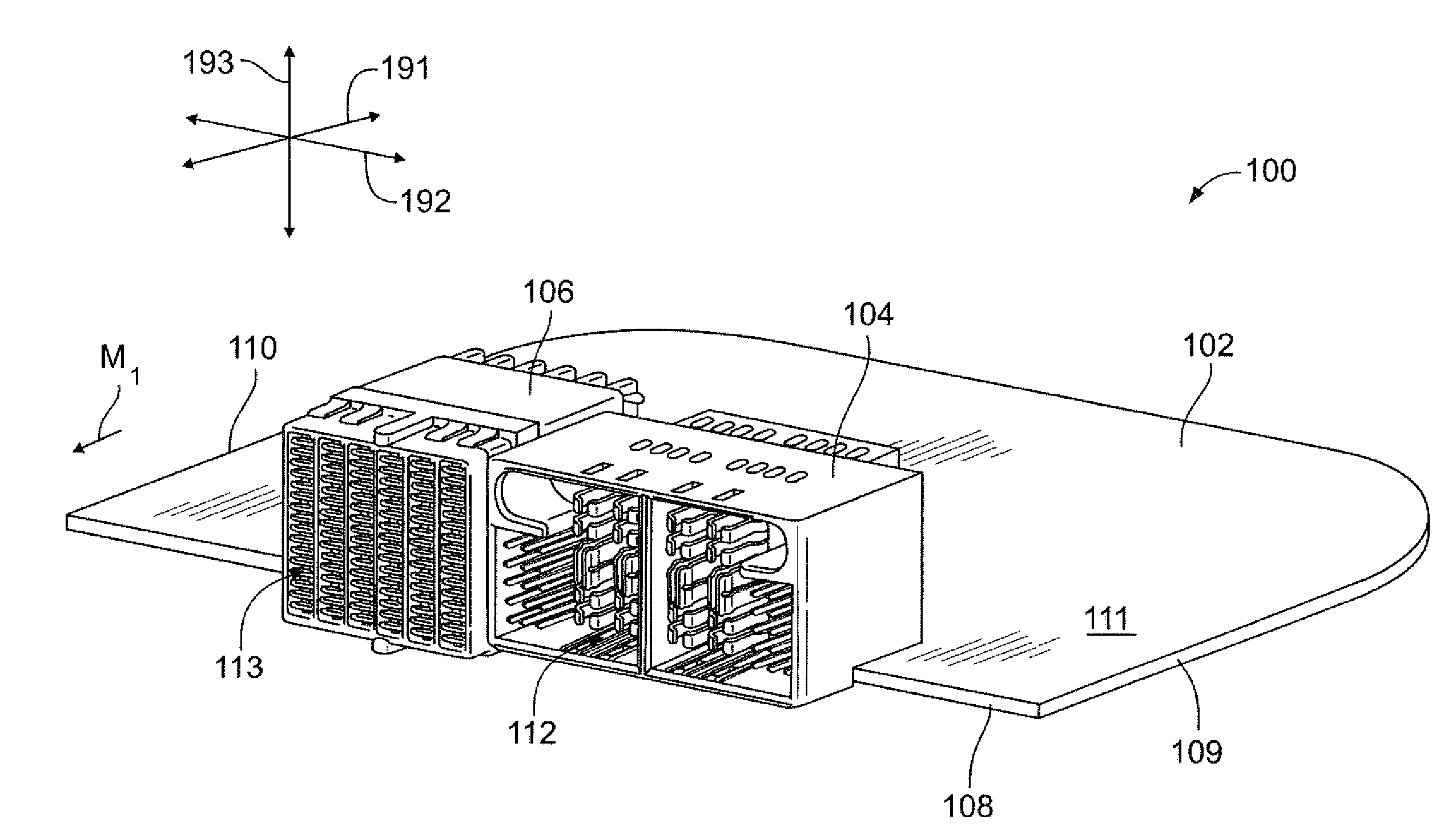
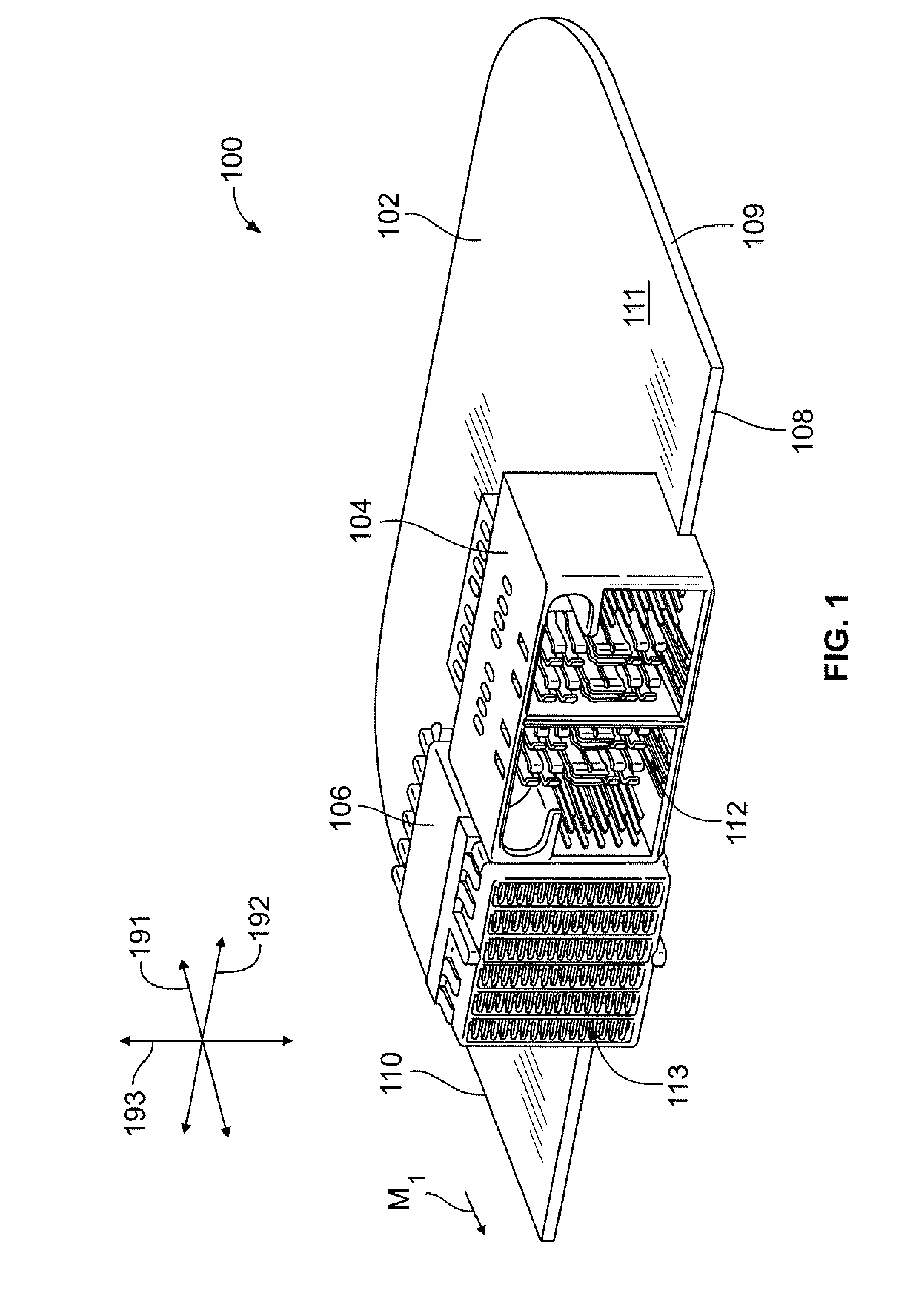
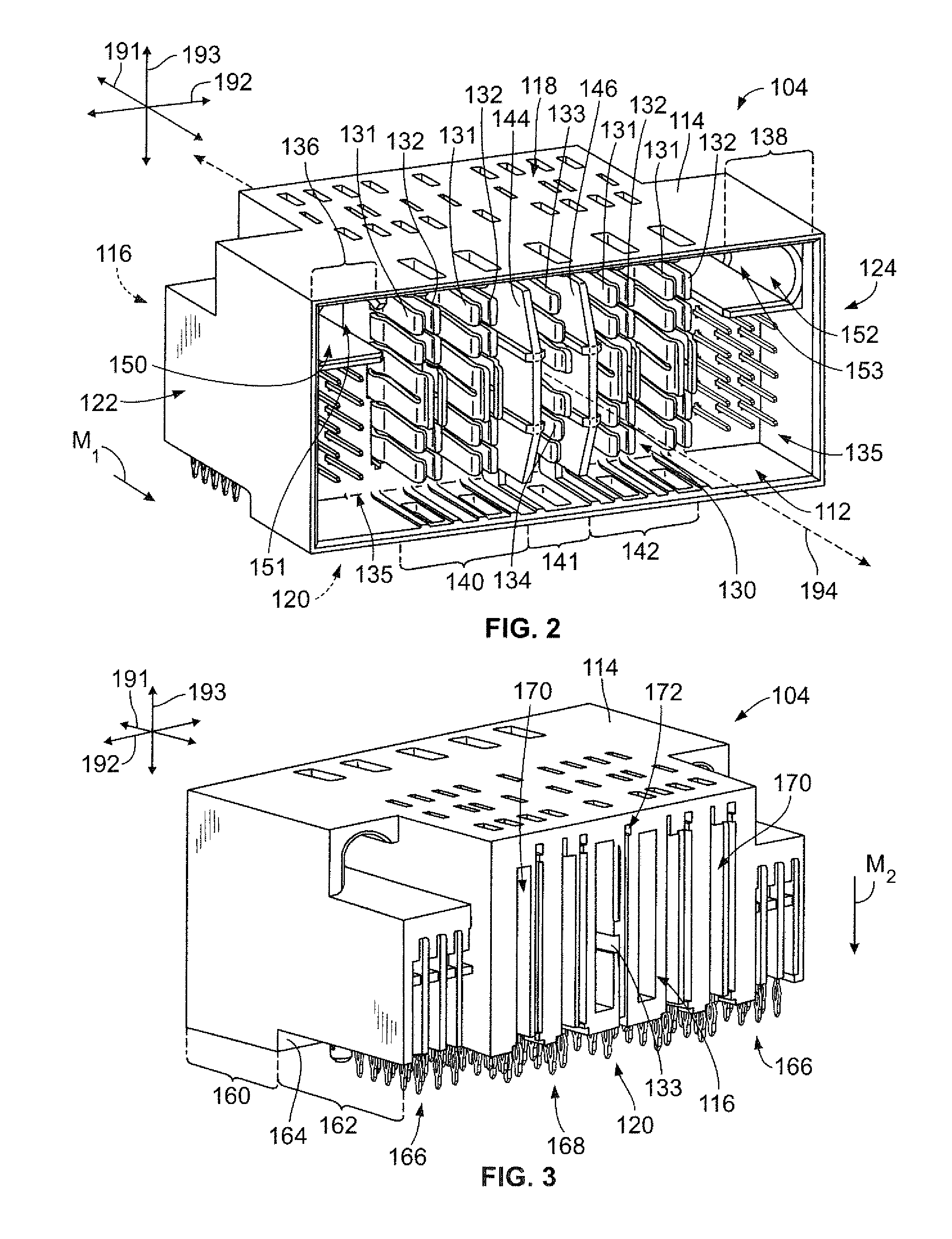
[0028]Embodiments described herein include electrical connectors having a mating side that is configured to engage another connector (hereinafter referred to as a mating connector). The electrical connector includes at least one electrical contact having a plurality of contact beams arranged along the mating side that are configured to engage corresponding contacts of the mating connector. In certain embodiments, the contact beams of one electrical contact have different dimensions, which may include different shapes or geometries. In some cases, the contact beams may be dimensioned differently with respect to one another to effectively reduce or control a mating force that is required to engage the electrical connector and the mating connector. Alternatively, or in addition to reducing the mating force, the contact beams may be dimensioned differently so that the contact beams vibrate or oscillate in different manners (e.g., different frequencies) when the electrical connector is e...


PUM


Abstract

Electrical connector including a connector housing having a mating side that faces in a mating direction. The mating side configured to engage a mating connector. The electrical connector also includes an electrical contact held by the connector housing. The electrical contact includes a common body section and first, second, and third contact beams that are arranged along the mating side and have respective contact bases coupled to the body section. Each of the first, second, and third contact beams extend in the mating direction from the respective contact base to a respective distal end. Each of the first, second, and third contact beams has a beam length that is measured from the respective contact base to the respective distal end. The beam lengths of the first, second, and third contact beams being different from one another.

Description

CROSS-REFERENCE TO RELATED APPLICATION[0001]The present application claims the benefit of Chinese Patent Application No. 201310111077.1, filed on Apr. 1, 2013, which is incorporated herein by reference in its entirety.BACKGROUND[0002]The subject matter herein relates generally to an electrical connector that has at least one electrical contact with a plurality of contact beams that engage corresponding contacts of another connector during a mating operation.[0003]Electrical connectors provide communicative interfaces between electrical components where power and / or signals may be transmitted therethrough. Electrical connectors may be used within telecommunication equipment, servers, and data storage or transport devices. For example, in some communication systems, an electrical connector is mounted along a leading edge of a circuit board to form a circuit board assembly. The electrical connector typically includes a plurality of electrical contacts that are capable of transmitting e...

Claims


Application Information

Patent Timeline
Patent Type & Authority Applications(United States)
IPC IPC(8): H01R13/05H01R12/70
CPCH01R12/7082H01R13/05H01R12/724H01R27/02H01R12/721
Inventor YUQIANG, ZHAONICHOLS, ROBERT PAULGUANGMING, ZHAOBLANCHFIELD, MICHAEL ALLEN
Owner TYCO ELECTRONICS (SHANGHAI) CO LTD
Learn More