
Camera module

a technology of camera modules and modules, applied in the field of camera modules, can solve the problems of increased manufacturing costs, cumbersomeness, frequent shocks of small camera modules mounted on small electronic products, etc., and achieve the effect of reducing the gap formed in the camera modul

Active Publication Date: 2014-10-16
LG INNOTEK CO LTD
View PDF2 Cites 17 Cited by
  • Summary
  • Abstract
  • Description
  • Claims
  • Application Information

AI Technical Summary

Benefits of technology

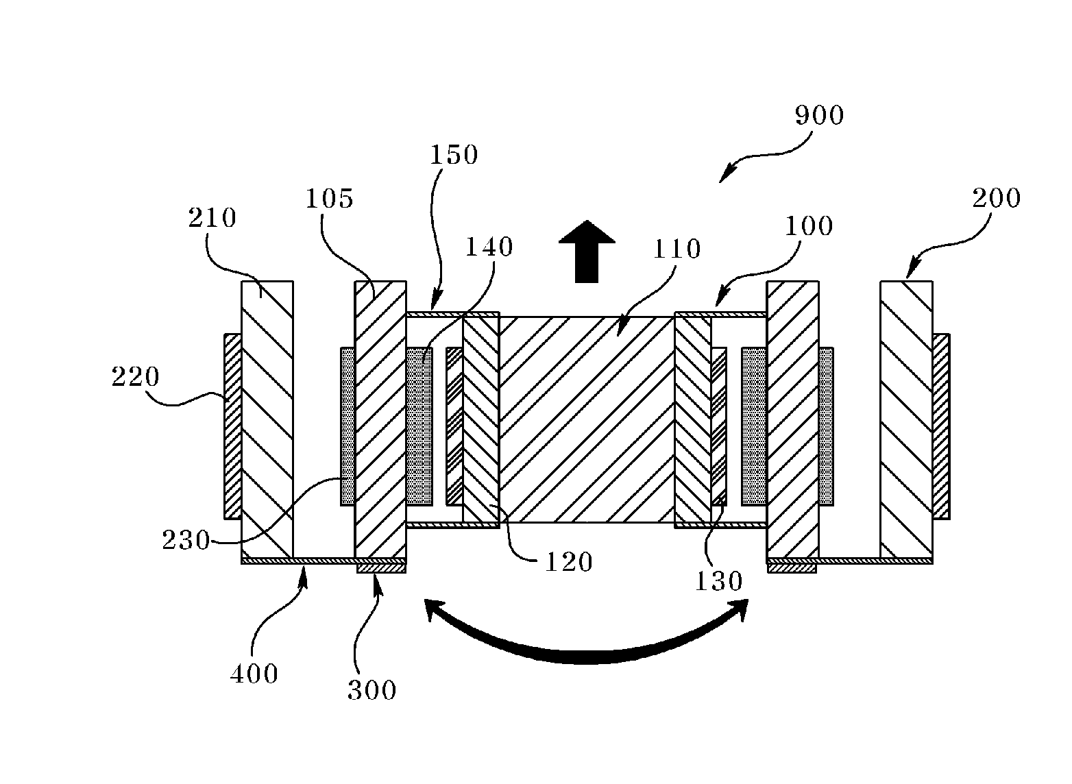
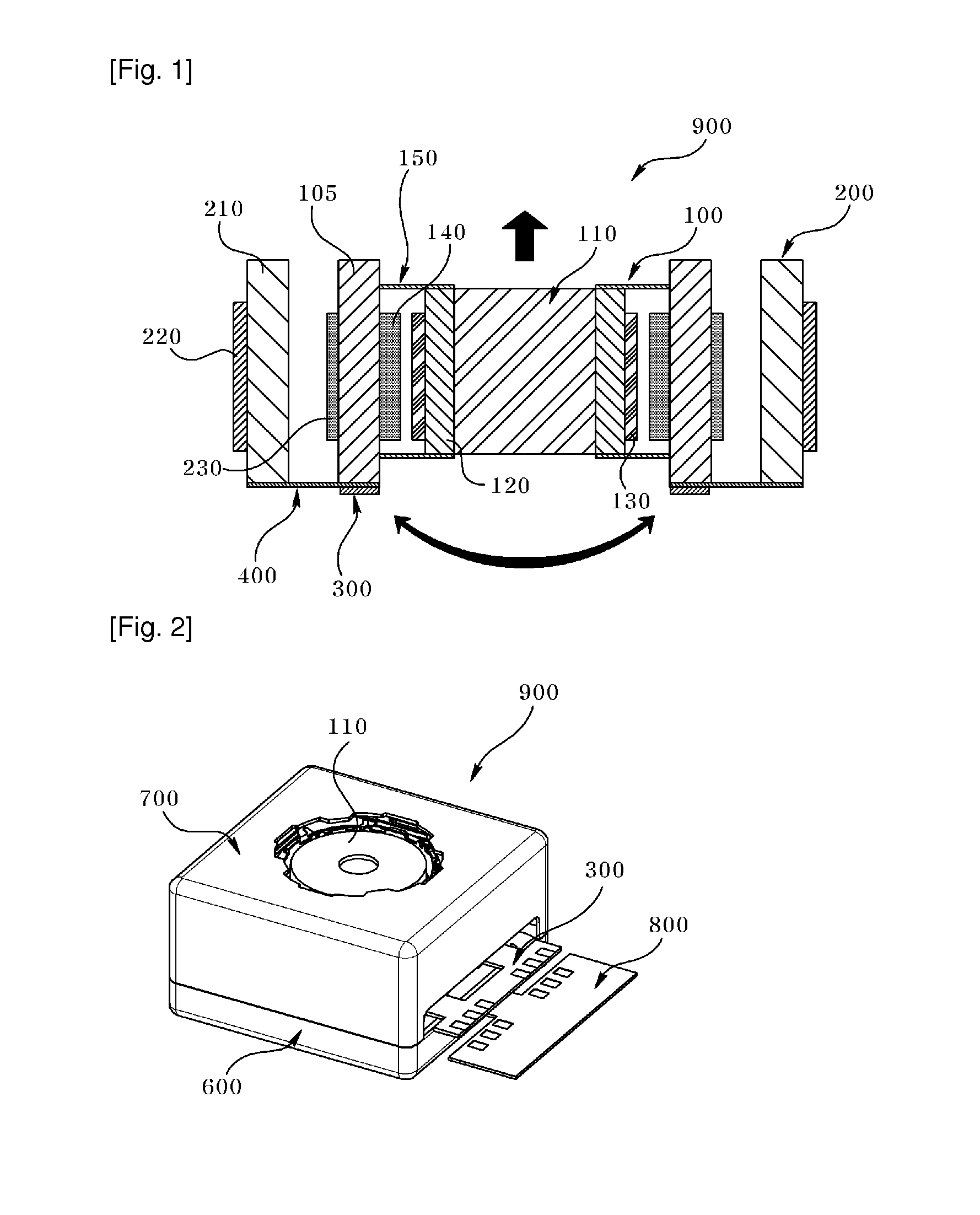
The present invention provides a camera module that uses an auto focusing module to move the lens vertically and compensates for handshake by tilting the module. An opening is formed to prevent erroneous tilting. Additionally, a part of the flexible printed circuit board (FPCB) acts as an elastic member to minimize the gap between the FPCB and the main circuit board, allowing for a smaller camera module.

Problems solved by technology

Small camera modules mounted on small electronic product often suffer from frequent shocks during use.
This is caused by subtle vibration from a user handshake or trembling during photographing process.
However, installation of a separate angular velocity sensor needs a separate detection sensor for realizing the handshake compensation function, resulting in an increased manufacturing cost and cumbersomeness of providing a space for configuring and installing a handshake prevention device aside from the camera module.

Method used


Image

  • Camera module
  • Camera module
  • Camera module

Examples


Embodiment Construction

[0026]The suffixes module’, ‘unit’ and ‘part’ may be used for elements in order to facilitate the disclosure. Significant meanings or roles may not be given to the suffixes themselves and it is understood that the ‘module’, ‘unit’ and ‘part’ may be used together or interchangeably.

[0027]The following description is not intended to limit the invention to the form disclosed herein. Consequently, variations and modifications commensurate with the following teachings, and skill and knowledge of the relevant art are within the scope of the present invention. The embodiments described herein are further intended to explain modes known of practicing the invention and to enable others skilled in the art to utilize the invention in such, or other embodiments and with various modifications required by the particular application(s) or use(s) of the present invention.

[0028]The disclosed embodiments and advantages thereof are best understood by referring to FIGS. 1-4 of the drawings, like numera...


PUM


Abstract

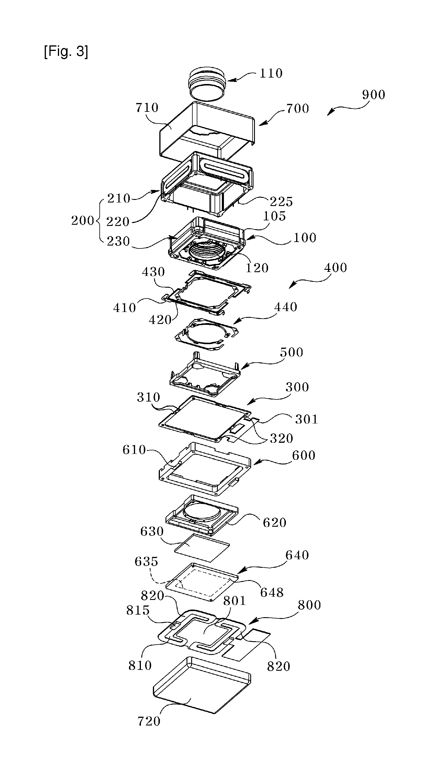
The present invention relates to a camera module including an auto focusing module vertically moving a lens, a handshake compensation module wrapping the auto focusing module, and tilting the auto focusing module to compensate handshake, a circuit board electrically connected to the handshake compensation module, a bottom case supporting the circuit board and coupled to the auto focusing module, a main circuit board fixed to bottom case and electrically connected to an image sensor module and the circuit board, and a spring unit arranged at a periphery of the main circuit board and having a symmetrical opening having thereinside a gap spaced apart at a predetermined distance.

Description

TECHNICAL FIELD[0001]The teachings in accordance with exemplary embodiments of this invention relate generally to a camera module applicable to smart phones and the like.BACKGROUND ART[0002]Small camera modules mounted on small electronic product often suffer from frequent shocks during use. This is caused by subtle vibration from a user handshake or trembling during photographing process. In consideration of the disadvantage, camera modules having anti-handshake means have been recently disclosed.[0003]One known art in the related field, Korean Registered Patent No.10-0741823 (registered on Jul. 16, 2007) teaches an hand-shake (hand vibration) compensation mechanism, where a gyro sensor IC (Integrated Circuit) or an angular velocity sensor is installed inside a device such as a mobile phone mounted with a camera module.[0004]However, installation of a separate angular velocity sensor needs a separate detection sensor for realizing the handshake compensation function, resulting in a...

Claims


Application Information

Patent Timeline
Patent Type & Authority Applications(United States)
IPC IPC(8): H04N5/232
CPCH04N5/23212H04N5/23287G03B17/04G03B3/10G03B5/00H04N23/57H04N23/55H04N23/687G03B3/02G03B30/00G03B17/02G02B27/646G03B2217/005G03B2217/002H04N23/54H04N23/68
Inventor KIM, EUN MI
Owner LG INNOTEK CO LTD
Learn More