Compound eye camera module and method of producing the same

a camera module and compound eye technology, applied in the field of small and thin camera modules, can solve the problems of insufficient thinning, and achieve the effects of reducing cost, thin camera modules, and miniaturizing camera modules

Active Publication Date: 2012-06-05
PANASONIC INTELLECTUAL PROPERTY CORP OF AMERICA
View PDF23 Cites 51 Cited by
  • Summary
  • Abstract
  • Description
  • Claims
  • Application Information

AI Technical Summary

Benefits of technology

[0016]According to the present invention, a light shielding block provided with light shielding walls is used in order to prevent light from being incident upon an imaging region from a lens not corresponding to the imaging region, so that a thin camera module can be realized.
[0017]Furthermore, in a camera module of the present invention, a light shielding block has a first sliding surface, and a lens module has a second sliding surface that slides on the first sliding surface. Furthermore, according to a production method of the present invention, the lens module is rotated with respect to the light shielding block with an axis normal to a plurality of imaging regions as a rotation center axis, and then, the lens module and the light shielding block are fixed to each other. Consequently, an image forming region of a lens does not extend off the imaging region, and it is not necessary to use a large imaging element having a number of unnecessary pixels, either. Thus, the camera module can be miniaturized and its cost can be reduced.
[0018]Accordingly, a thin, small, and low-cost compound eye camera module can be provided.

Problems solved by technology

More specifically, the camera module in FIG. 13 has a problem that thinning is insufficient.

Method used


Image

  • Compound eye camera module and method of producing the same
  • Compound eye camera module and method of producing the same
  • Compound eye camera module and method of producing the same

Examples


embodiment 1

[0044]Hereinafter, Embodiment 1 of the present invention will be described with reference to the drawings.

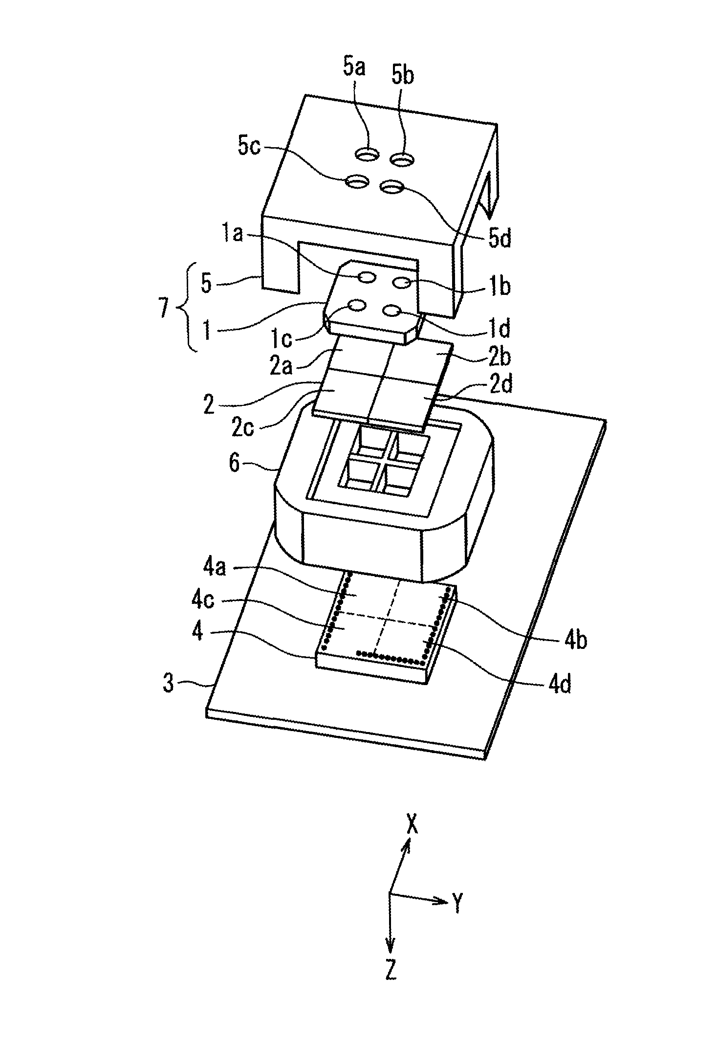
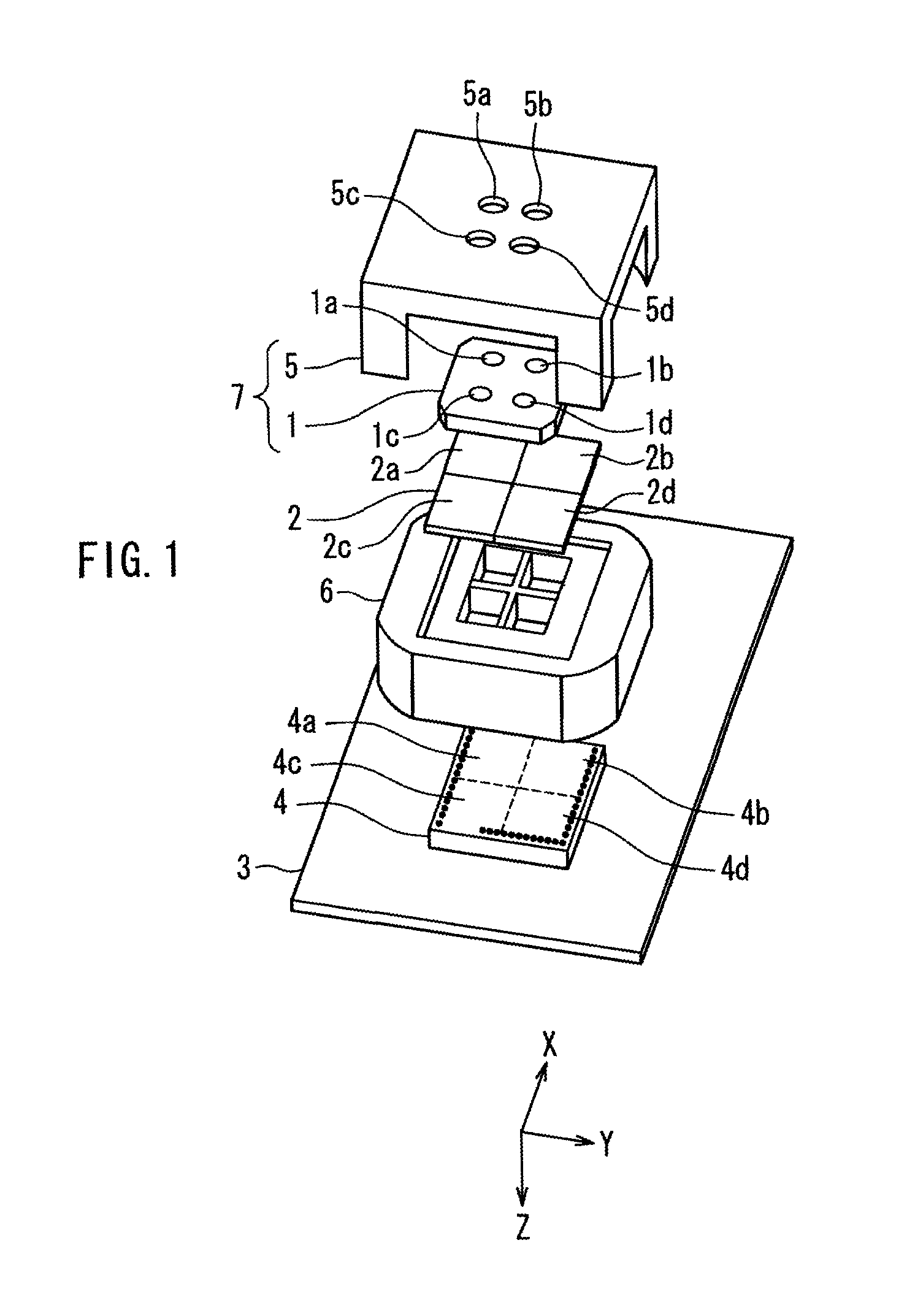
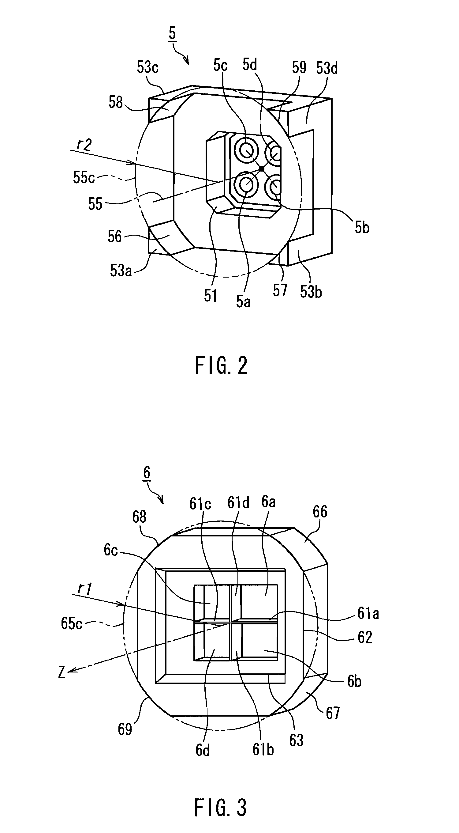
[0045]FIG. 1 is an exploded perspective view of a compound eye camera module of Embodiment 1. In FIG. 1, reference numeral 1 denotes a lens array, 2 denotes an optical filter array, 3 denotes a substrate, 4 denotes an imaging element, 5 denotes an upper barrel, 6 denotes a light shielding block (lower barrel), and 7 denotes a lens module. For convenience of the description, an XYZ rectangular coordinate system as shown is assumed. Herein, a Z-axis passes through substantially the center of an effective pixel region of the imaging element 4 and is normal to the effective pixel region. An X-axis is orthogonal to the Z-axis and parallel to light shielding walls 61a, 61c (described later) of the light shielding block 6, and a Y-axis is orthogonal to the Z-axis and parallel to light shielding walls 61b, 61d (described later) of the light shielding block 6.

[0046]The lens array 1 integ...

embodiment 2

[0079]Hereinafter, Embodiment 2 of the present invention will be described with reference to the drawings.

[0080]FIG. 6 is an exploded perspective view of a compound eye camera module of Embodiment 2. In FIG. 6, the same members as those in FIG. 1 are denoted with the same reference numerals as those therein, and the description thereof will be omitted.

[0081]The basic configuration of the camera module of the present embodiment is substantially the same as that of Embodiment 1. The present embodiment is different from Embodiment 1 in the shapes of an upper barrel 500 and a light shielding block 600.

[0082]FIG. 7 is a perspective view of the upper barrel 500 seen from a subject side. The upper barrel 500 in the present embodiment is different from the upper barrel 5 in Embodiment 1 in that grooves 501, 502 are provided on two opposed side surfaces.

[0083]FIG. 8 is a perspective view of the light shielding block 600 seen from the subject side. The light shielding block 600 in the present...

embodiment 3

[0089]The lens array 1 having a plurality of lenses can be obtained integrally, for example, by molding a lens material (e.g., resin or glass) with a mold. In such a case, the optical axis positions of a plurality of lenses on the obtained lens array may be displaced from desired positions due to the production error of the mold, the molding error, etc. For example, as shown in FIG. 11A, there is a case in which a quadrangle with the optical axis positions 11a to 11d of the four lenses 1a to 1d (not shown) arranged in a lattice point shape as apexes may not exactly be a rectangle. In such a case, even if the lens module 7 is adjusted by rotation with respect to the light shielding blocks 6, 600 so that the image-forming regions 13a to 13d of the lenses 1a to 1d do not extend off the imaging regions 4a to 4d, for example, in the case where the distance to a subject is measured with a camera module, using the principle of triangulation, there arise problems in that the measurement pre...


PUM


Abstract

An optical filter array (2) having a plurality of optical filters (2a to 2d) and a light shielding block (6) having light shielding walls (61a to 61d) forming a plurality of openings (6a to 6d) independent from each other are placed between a lens module (7) integrally having a plurality of lenses (1a to 1d) arranged on a single plane and a plurality of imaging regions (4a to 4d). The light shielding block is provided with first sliding surfaces (66 to 69). The lens module is provided with second sliding surfaces (56 to 59) sliding on the first sliding surfaces so that the lens module can rotate with respect to the light shielding block with an axis normal to the plurality of imaging regions as a rotation center axis. Thus, a small, thin, and low-cost compound eye camera module can be realized.

Description

TECHNICAL FIELD[0001]The present invention relates to a small and thin camera module, and a method of producing the camera module. In particular, the present invention relates to a compound eye camera module that captures an image with a plurality of photographing optical lenses, and a method of producing the camera module.BACKGROUND ART[0002]In an imaging apparatus such as a digital video and a digital camera, a subject image is formed on an imaging element such as a CCD or a CMOS through a lens, whereby a subject is converted into two-dimensional image information. A camera module to be mounted on such an imaging apparatus is required to be small and thin.[0003]In order to realize a small and thin camera module, a compound eye camera module has been proposed.[0004]One example of the compound eye camera module is described in Patent Document 1, and will be described with reference to FIG. 13. A lens array 100 including three lenses 100a, 100b, and 100c and an imaging element 105 ar...

Claims


Application Information

Patent Timeline
Patent Type & Authority Patents(United States)
IPC IPC(8): G02B13/16H04N5/225G02B21/00H01L27/00G02B7/02G03B11/00G03B15/00H04N5/335H04N5/349
CPCH04N5/2254H04N5/2257H04N23/57H04N23/55H04N25/41
Inventor TAMAKI, SATOSHIIMADA, KATSUMISUENAGA, TATSUTOSHI
Owner PANASONIC INTELLECTUAL PROPERTY CORP OF AMERICA
Why Eureka
Try Eureka