Zero Clearance Combination Oven

Active Publication Date: 2014-10-23
ALTO SHAAM
View PDF52 Cites 3 Cited by
  • Summary
  • Abstract
  • Description
  • Claims
  • Application Information

AI Technical Summary

Benefits of technology

[0006]The present invention provides an oven with a “zero clearance” outer wall having an internal air circulation plenum just inside the outer wall. By providing forced airflow through the plenum, the plenum internalizes otherwise necessary external clearance distances bu

Problems solved by technology

This close proximity results in substantial heat transfer from the cooking cavity and the electrical compartment which, if unaddressed, would unacceptably raise the temperature of t

Method used


Image

  • Zero Clearance Combination Oven
  • Zero Clearance Combination Oven
  • Zero Clearance Combination Oven

Examples


Embodiment Construction

Zero Clearance Sidewall

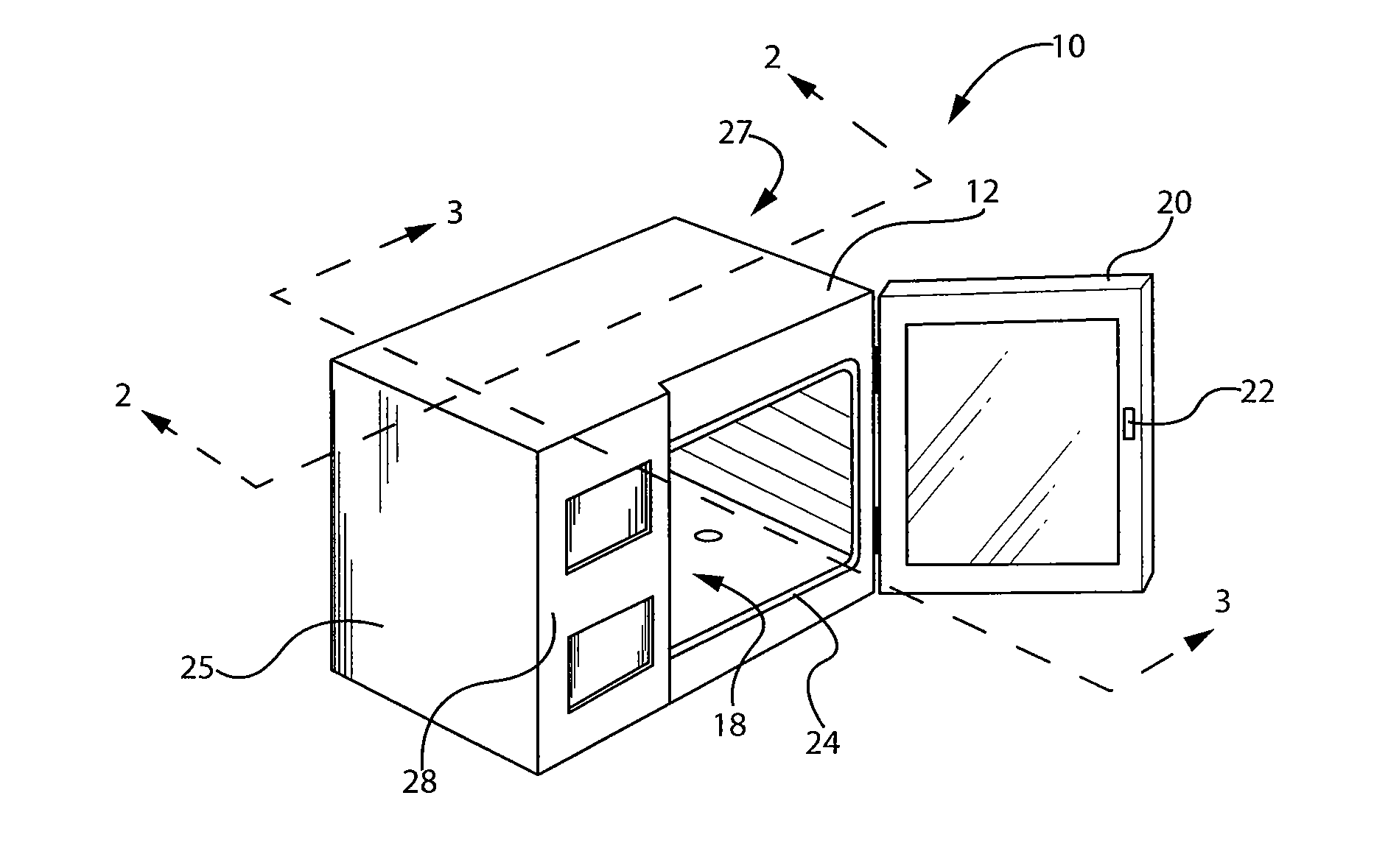
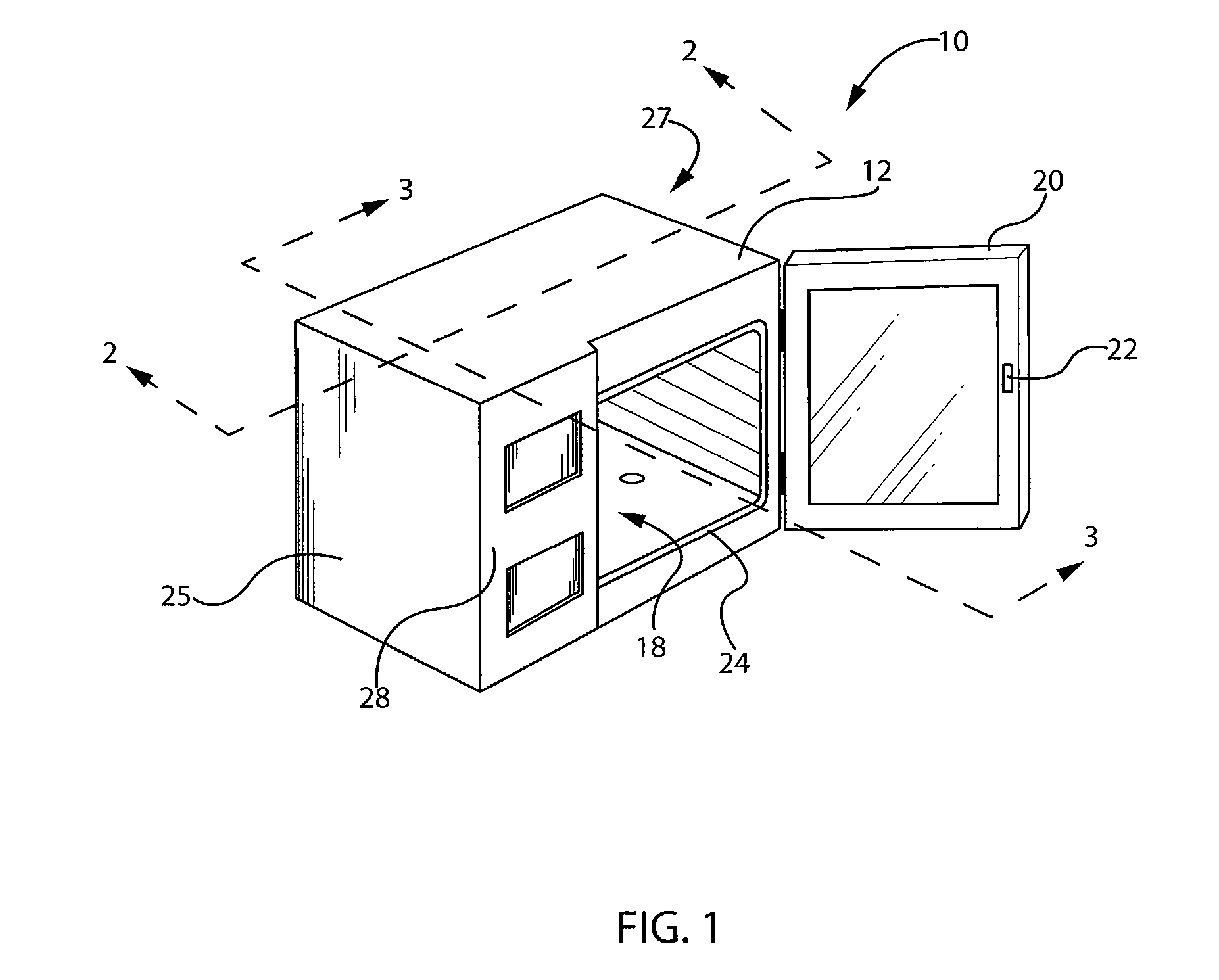
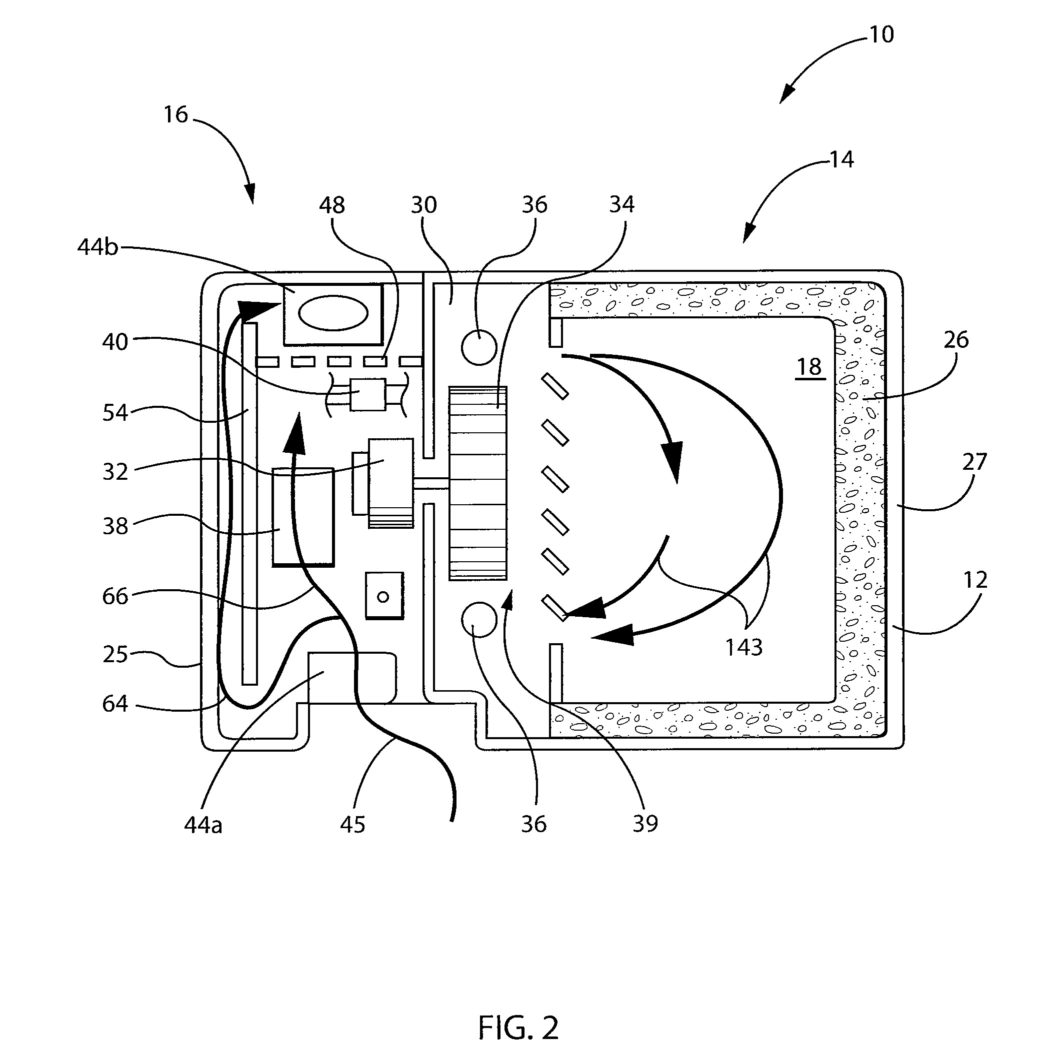
[0045]Referring now to FIG. 1, a “zero clearance” oven 10 according to one embodiment of the present invention may provide an oven housing 12 internally divided into an oven compartment 14 and an equipment compartment 16.

[0046]The oven compartment 14, in turn, holds an oven cavity 18 that may be accessed through a door 20, the latter connected by a hinge at one vertical side of the oven cavity 18. As is generally understood in the art, the door 20 may close over the oven cavity 18 during cooking operation as held by a latch assembly 22 (visible on the door 20 only). In the closed position, the door 20 may substantially seal against the oven cavity 18 by compressing against a gasket 24 surrounding an opening of the oven cavity 18 in the housing 12. Sidewalls of the oven cavity 18 may provide for rack supports 11 holding conventional cooking racks for supporting pans or trays of food.

[0047]The equipment compartment 16 is positioned to the side of the oven compa...


PUM


Abstract

A commercial oven, such as a combination oven providing steam and convection heating, may provide an equipment cabinet holding electronic equipment and having an external wall abutting other heating apparatus. The external wall includes an interior plenum through which air is circulated to provide compact virtual insulation from external heat sources.

Description

BACKGROUND OF THE INVENTION [0001]The present invention relates to commercial ovens and in particular to an oven that may be placed closely adjacent to other heating devices.[0002]Commercial ovens may include features such as forced and heated airflow through the cooking cavity (convection cooking) and the introduction of steam into the cooking cavity (steam cooking). The fan motor for convection cooking, the water handling system for steam cooking, and control electronics for each are normally held in an equipment compartment that is maintained at a substantially lower temperature than the cooking cavity compatible with electrical and electromechanical components.[0003]The equipment compartment is normally adjacent to the cooking cavity to provide for the necessary mechanical and electrical connections between equipment of the equipment compartment and the fan, steam nozzles, and sensors within the cooking cavity. This close proximity results in substantial heat transfer from the c...

Claims


Application Information

Patent Timeline
IPC IPC(8): F24C15/00F24C3/00
CPCF24C3/004F24C15/006F24C13/00
Inventor RAGHAVAN, J.K.SIMMELINK, ROBERTBARTELICK, JANUS
Owner ALTO SHAAM
Why Eureka
Try Eureka