Plug tool for plugging or unplugging connector

Inactive Publication Date: 2014-10-23
HONG FU JIN PRECISION IND (SHENZHEN) CO LTD +1
View PDF12 Cites 1 Cited by
  • Summary
  • Abstract
  • Description
  • Claims
  • Application Information

AI Technical Summary

Benefits of technology

The present patent is about a plug tool for connecting and disconnecting connectors to a switch. The technical effect of the invention is to provide a tool that makes it easier and more convenient to plug and unplug connectors, especially in cases where the connectors are small and difficult to reach with hands. The plug tool includes a fastening shell and a sleeve made of resilient material, which are designed to fit snugly around the plug and connector, and a rotating pole that can be rotated to secure the connection. The tool is easy to assemble and use, and can be easily detached from the switch.

Problems solved by technology

However, plugging or unplugging a connector by hand can be difficult and inconvenient because of limited or cramped operation space.

Method used


Image

  • Plug tool for plugging or unplugging connector
  • Plug tool for plugging or unplugging connector
  • Plug tool for plugging or unplugging connector

Examples


Embodiment Construction

[0009]The disclosure, including the accompanying drawings, is illustrated by way of example and not by way of limitation. It should be noted that references to “an” or “one” embodiment in this disclosure are not necessarily to the same embodiment, and such references mean at least one.

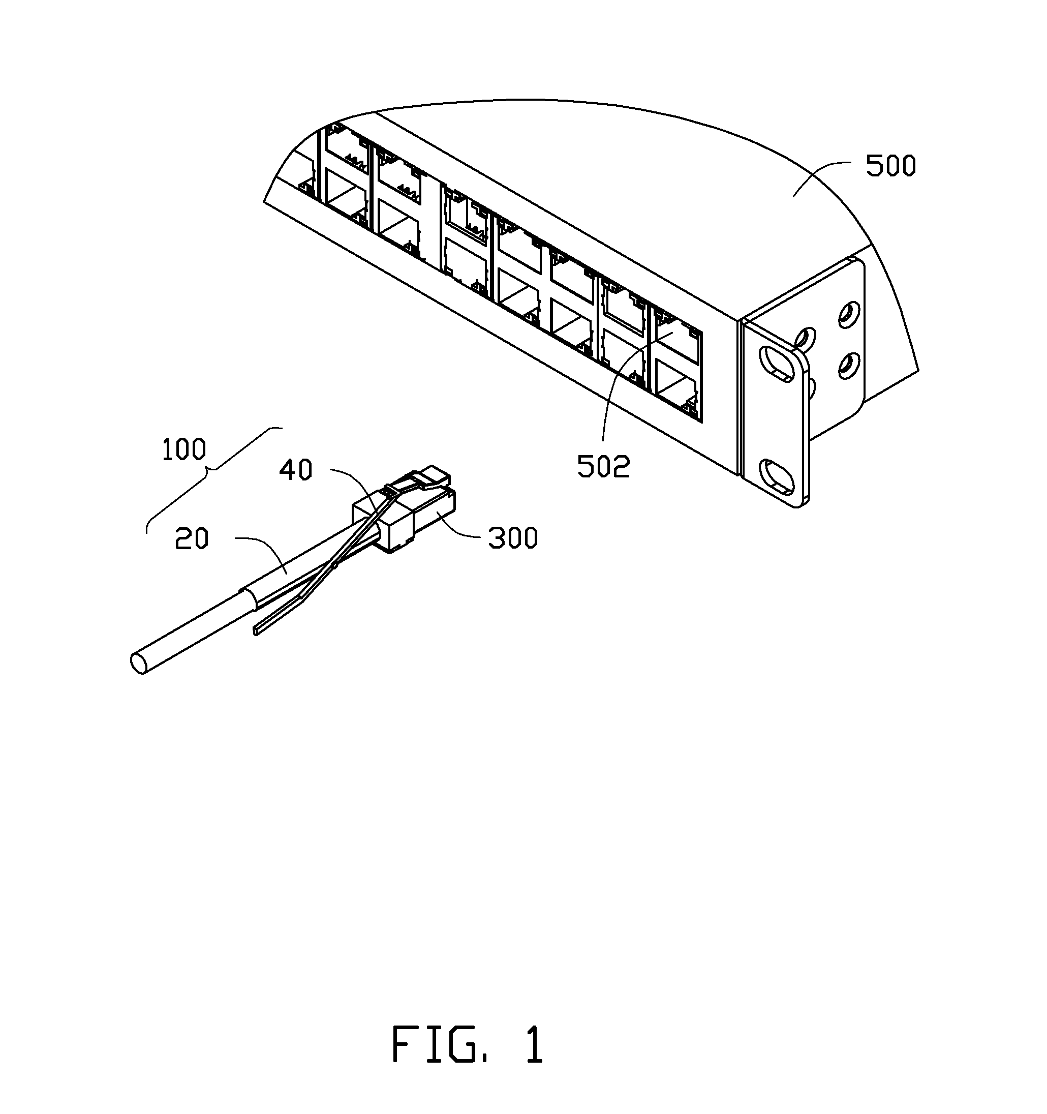
[0010]FIG. 1 shows an embodiment of a plug tool 100 used to mount a connector 300. The connector 300 is plugged to a switch 500 or unplugged from the switch 500 with the plug tool 100. The switch 500 includes a plurality of interfaces 502. The plug tool 100 includes a first operation member 20 and a second operation member 40.

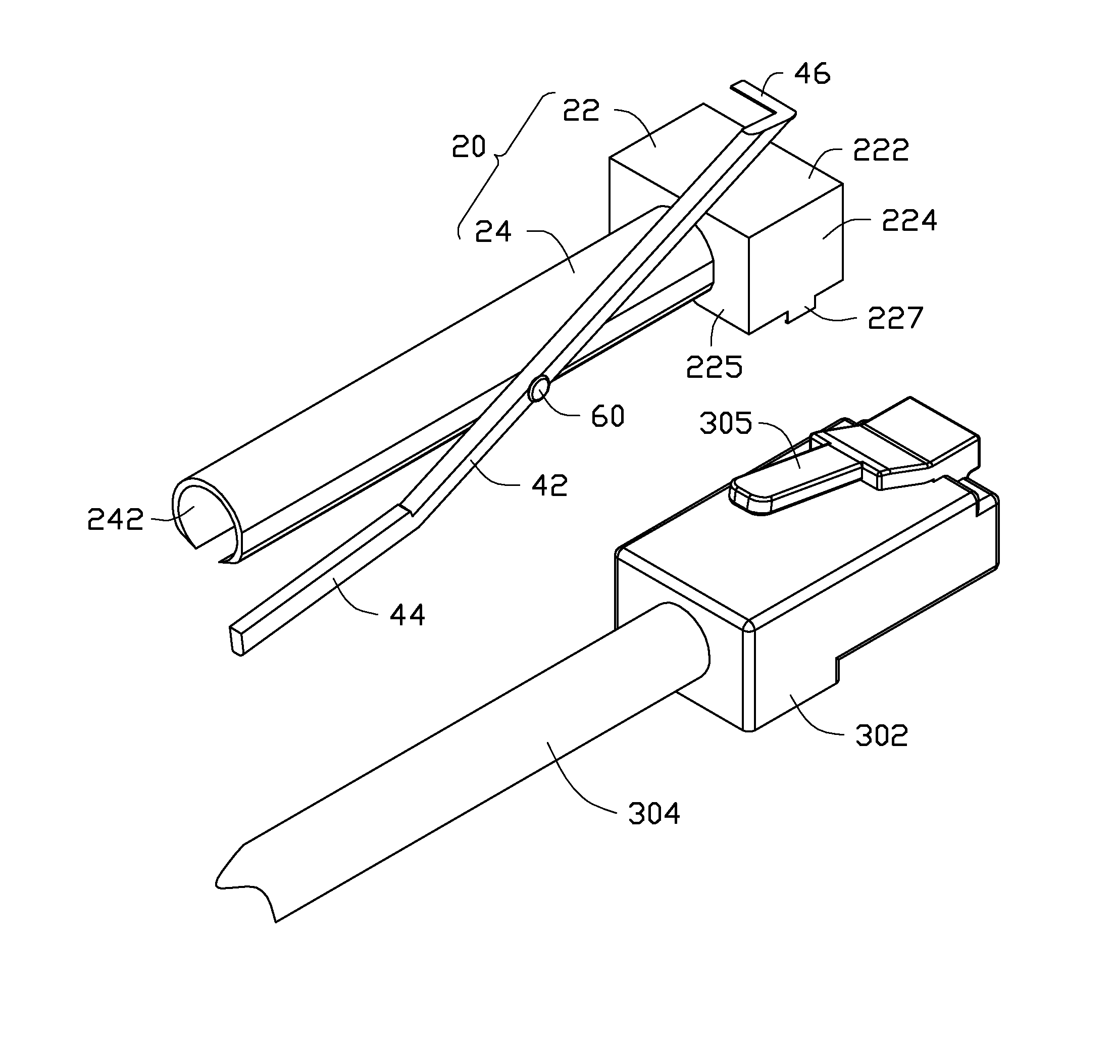
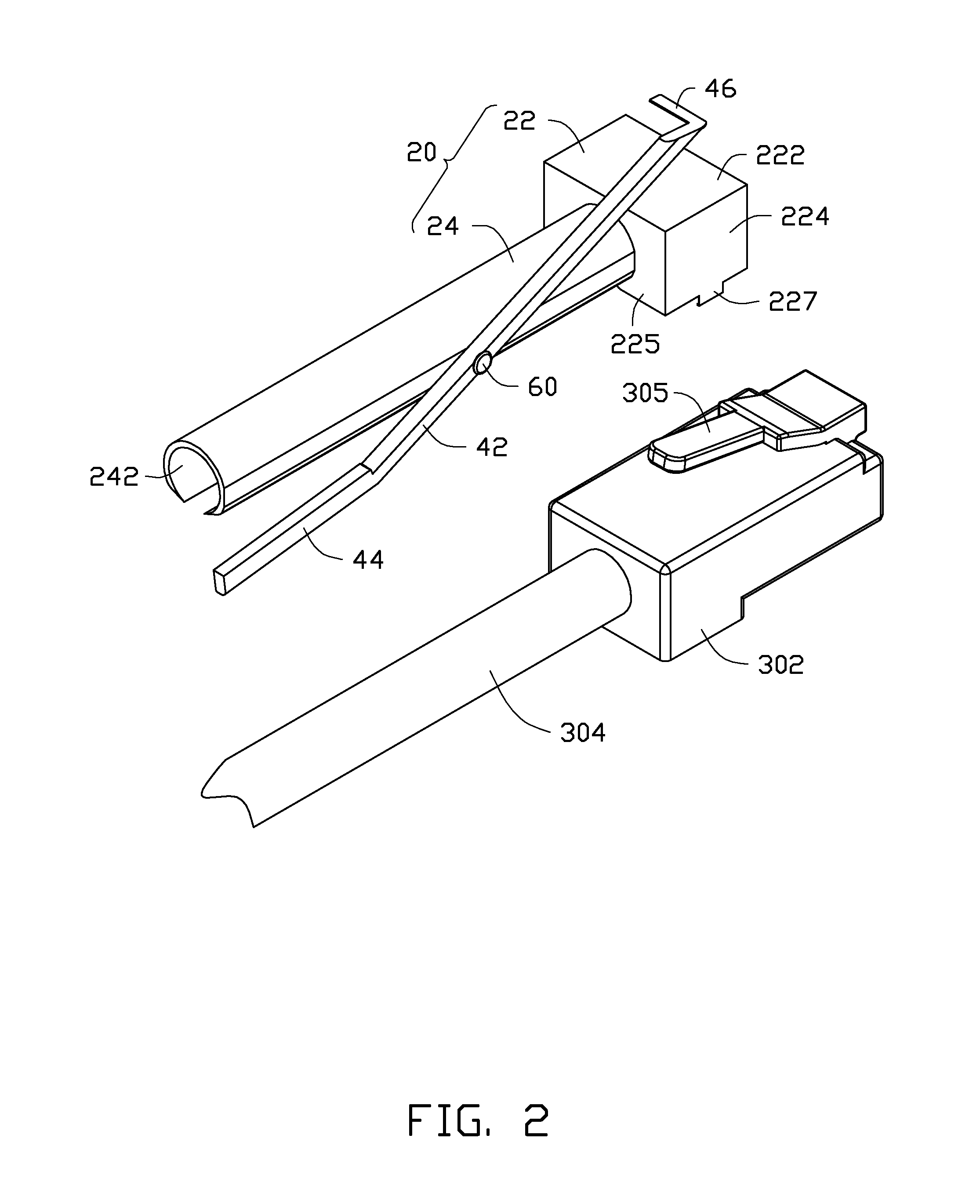
[0011]FIGS. 2 and 3 show the plug tool 100 together with the connector 300. The connector 300 includes a plug 302 and a cable 304 electrically connected to the plug 302. A resilient latching piece 305 slantingly extends rearward and up from a front end of a top of the plug 302. A rear end of a bottom of the plug 302 defines a latching slot 306.

[0012]The first operation member 20 i...


PUM

PropertyMeasurementUnit
Resilienceaaaaaaaaaa

Abstract

A plug tool for plugging or unplugging a connector includes a first operation member and a second operation member. The connector includes a plug, a resilient latching piece, and a cable. The first operation member includes a fastening shell receiving the plug and a sleeve extending out from the fastening shell receiving the cable of the connector. The second operation member is rotatably connected to the sleeve. The second operation member includes a pressing portion for pressing the latching piece of the connector toward the plug.

Description

BACKGROUND[0001]1. Technical Field[0002]The present disclosure relates to a plug tool for plugging or unplugging a connector.[0003]2. Description of Related Art[0004]For a certain type of switch, a great number of small-sized connectors need to be connected to the switch. However, plugging or unplugging a connector by hand can be difficult and inconvenient because of limited or cramped operation space.BRIEF DESCRIPTION OF THE DRAWINGS[0005]Many aspects of the present embodiments can be better understood with reference to the following drawings. The components in the drawings are not necessarily drawn to scale, the emphasis instead being placed upon clearly illustrating the principles of the present embodiments. Moreover, in the drawing, all the views are schematic, and like reference numerals designate corresponding parts throughout the several views.[0006]FIG. 1 is an exploded, isometric view of an embodiment of a plug tool together with a switch and a connector.[0007]FIG. 2 is an ...

Claims


Application Information

Patent Timeline
IPC IPC(8): H01R13/629H01R43/26H01R13/627
CPCH01R13/629H01R43/26H01R13/6275H01R13/6272H01R24/64Y10T29/53257
Inventor GAO, XIA-BINGHE, AI-LINGZHANG, HAN-BING
Owner HONG FU JIN PRECISION IND (SHENZHEN) CO LTD
Why Eureka
Try Eureka