
Wiper connector for vehicle

a technology for a vehicle and a connector is applied in the field of vehicle wiper connectors, which can solve the problems of only using dedicated wiper connectors, causing chattering,

Inactive Publication Date: 2014-11-20
KBWS CORP
View PDF9 Cites 25 Cited by
  • Summary
  • Abstract
  • Description
  • Claims
  • Application Information

AI Technical Summary

Benefits of technology

The invention is a device with a body and a cover that can move back and forth. The body has a recess on both sides where a protrusion on the cover can fit and guide the movement of the cover. The technical effect of this design is that it allows for easy assembly and disassembly of the device, and enables smooth movement of the cover without any bumps or uneven surfaces.

Problems solved by technology

The wiper blade has a problem in that the wiper blade lifts by an air pressure applied to a glass surface when the vehicle is driven at a high speed and chattering occurs.
That is, the conventional driving arm for the vehicle is largely classified into a “U” shaped clip type having a catching structure, a bayonet type fitted as a plug type, a pin type forming a protrusion in a side portion and taking a fitting structure by the protrusion, a side hole type performing a fitting coupling in a side portion of a wiper apparatus, developed by a Bosch corporation, and a top-lock type performing a coupling by a covering structure in an upper portion of the wiper apparatus, and the various types of driving arms have a limitation in that they can use only dedicated wiper apparatuses since their shapes and sizes are different from other.

Method used


Image

  • Wiper connector for vehicle
  • Wiper connector for vehicle
  • Wiper connector for vehicle

Examples


embodiment

[0131]FIGS. 9a and 9b are a front view and a perspective view respectively showing that a cover of the connector coupled to the wiper blade according to the present invention is located at a fixing position. FIGS. 9c and 9d are a front view and a perspective view respectively showing that the cover of the connector coupled to the wiper blade according to the present invention is located at a release position.

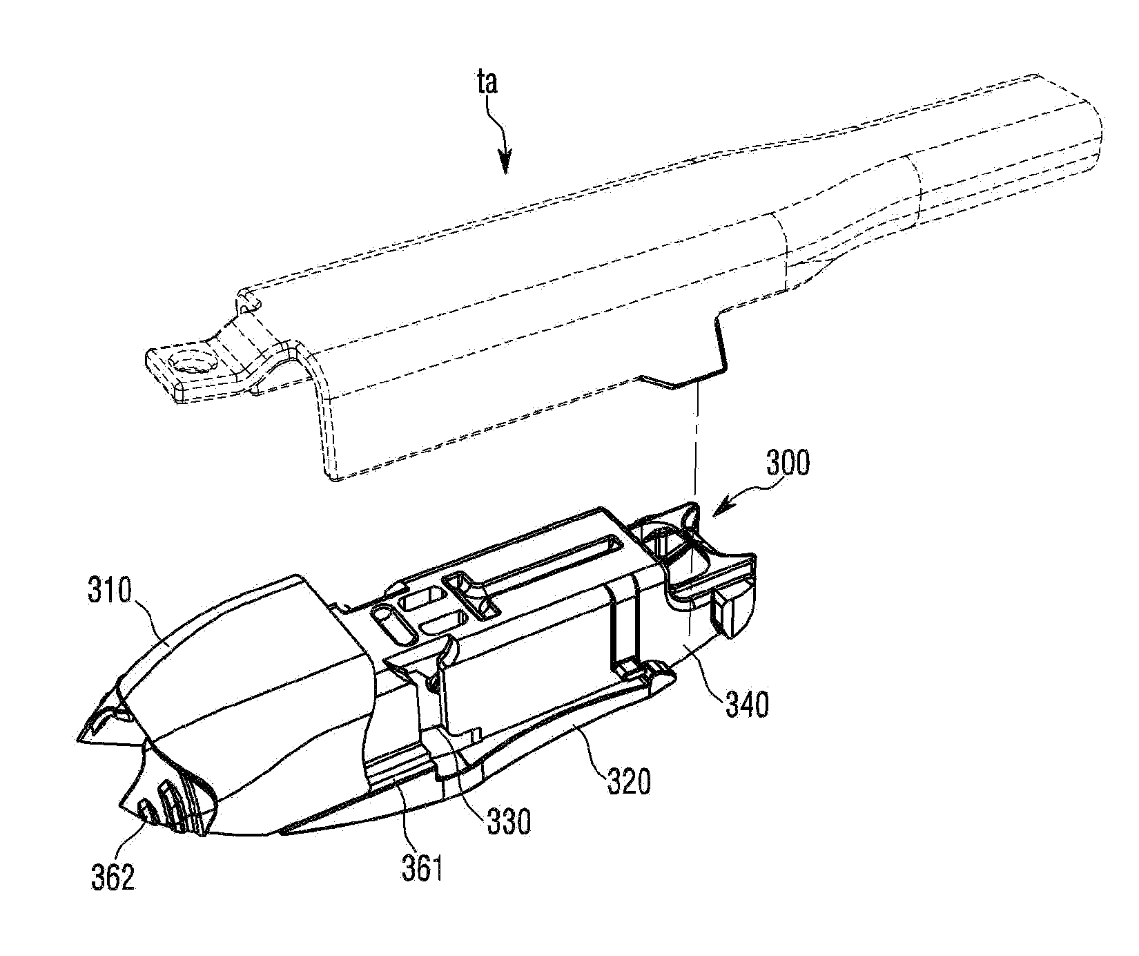
[0132]Referring to FIGS. 9a to 9d, the connector 300 includes a body 320 by which the wiper arm is caught, and the cover 310 which is able to move to the fixing position for fixing the wiper arm caught by the body 320 and to the release position for releasing the fixed wiper arm.

[0133]FIG. 10a is a perspective view showing the embodiment of the adaptor of the wiper blade according to the present invention. FIG. 10b is a sectional perspective view of the wiper blade according to the present invention. FIG. 10c is a plan view of the wiper blade according to the present invention a...

first embodiment

[0148]FIGS. 12a to 12d show the connector 300 which is mounted on the adaptor part 200. Referring to FIGS. 10a and 12c, the lower portion of the connector 300 is open to be coupled to the adaptor part 200. Referring to FIGS. 12a to 12d, the connector 300 includes the body 320 and the cover 310. The body 320 includes a pair of elastic moving pieces 362 which is formed on one end of the body 320 and faces each other, and one or more coupling parts 330 and 340 which are formed on both sides of the body 320 and by which the wiper arm is caught. The cover 310 is movable to the fixing position for fixing the wiper arm caught by the body 320 and to the release position for releasing the fixed wiper arm.

[0149]Referring to FIGS. 12a to 12d, the body 320 includes a fitting part 350 for the coupling to the adaptor part 200. The body 320 may include a first coupling part 330 and a second coupling part 340. The first coupling part 330 and the second coupling part 340 may be selectively connected...


PUM


Abstract

A wiper connector for a vehicle may be provided which connects a wiper arm to a wiper blade 10 and includes: a body 320 including a pair of elastic moving pieces 362 which is formed on one end thereof and faces each other, and one or more coupling parts 330 and 340 which are formed on both sides thereof and by which the wiper arm is caught; and a cover 310 movable to a fixing position for fixing the wiper arm which is caught by the body 320 and to a release position for releasing the fixed wiper arm. The pair of the elastic moving pieces 362 elastically restrains the movement of the cover 310 at the fixing position and allows the cover 310 to move to the release position when a releasing force for removing the elastic restraint is applied to the elastic moving piece 362.

Description

CROSS-REFERENCE TO RELATED APPLICATIONS[0001]The present application claims priority under 35 U.S.C. §119(a) to Korean Patent Application No. 10-2013-0054741, filed on May 15, 2013, which is incorporated by reference herein in its entirety.BACKGROUND[0002]1. Field[0003]The present invention relates to a wiper connector for a vehicle, which connects a wiper blade with a wiper arm.[0004]2. Description of Related Art[0005]In general, a wiper blade removes impurities, snow, rain or the like when driving and prevents a driver's front sight from being deteriorated and performs a repetitive reciprocating action in a fan shape as a motor drives a link apparatus connected to a wiper arm.[0006]A conventional wiper blade includes a lever assembly configured by connecting levers of metal materials in a tournament type. In the lever assembly, a plurality of tournament levers curve a wiper strip, so that the wiper strip having a backing plate installed therein traces a curvature of a vehicle glas...

Claims


Application Information

Patent Timeline
Patent Type & Authority Applications(United States)
IPC IPC(8): B60S1/40
CPCB60S2001/4061B60S1/4038B60S1/3801B60S1/4003B60S2001/3843B60S2001/4051B60S2001/4058B60S1/3806B60S1/38B60S1/40
Inventor AN, JAE HYUCKLEE, WOO SUNG
Owner KBWS CORP
Features
  • Generate Ideas
  • Intellectual Property
  • Life Sciences
  • Materials
  • Tech Scout
  • Unparalleled Data Quality
  • Higher Quality Content
  • 60% Fewer Hallucinations
Learn More