
Retractable Utility Rack

a utility rack and retractable technology, applied in the field of utility racks, can solve the problems of system instability, system obstacle to be worked around,

Inactive Publication Date: 2014-11-20
COUCH GEORGE
View PDF11 Cites 17 Cited by
  • Summary
  • Abstract
  • Description
  • Claims
  • Application Information

AI Technical Summary

Benefits of technology

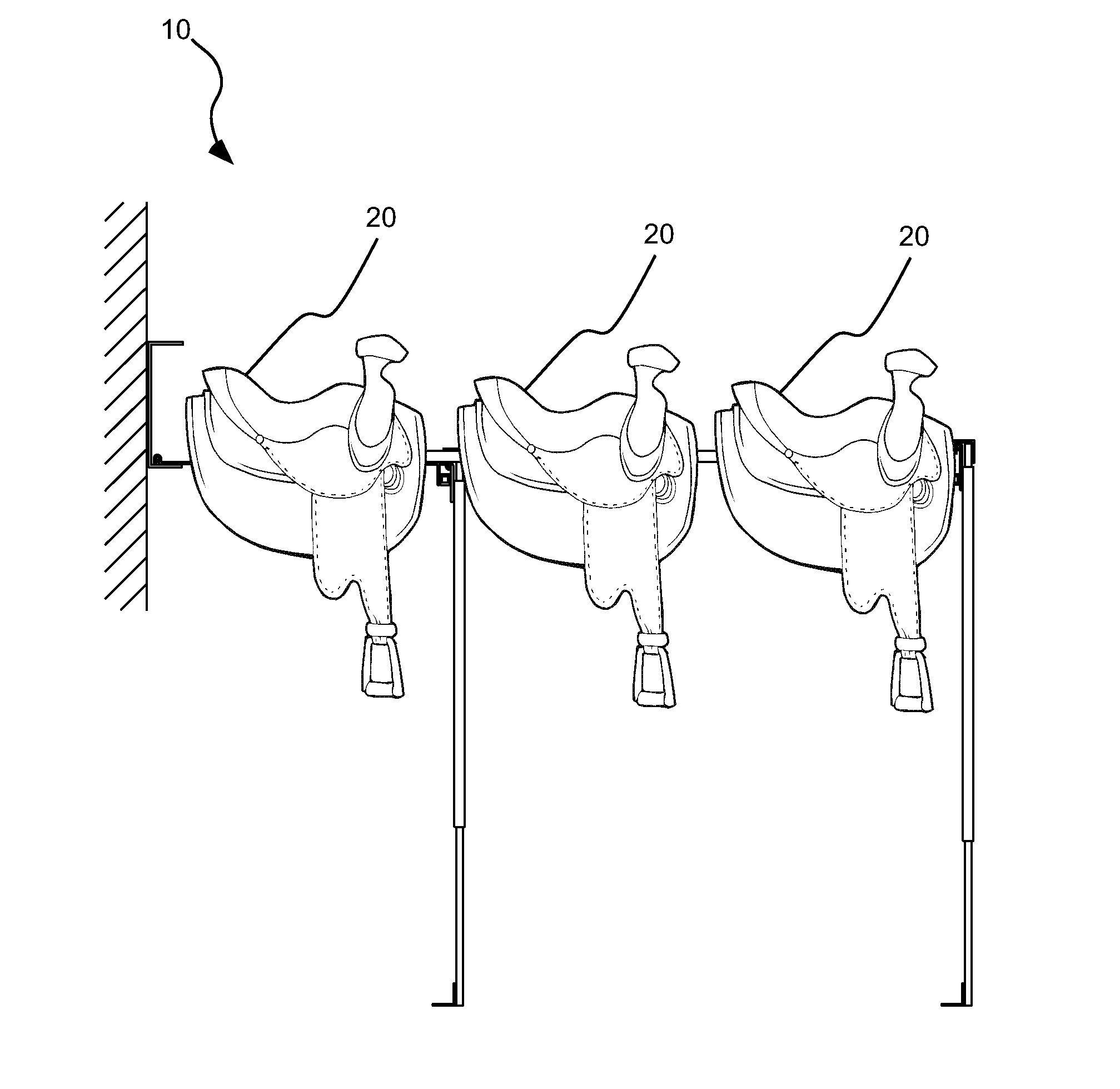
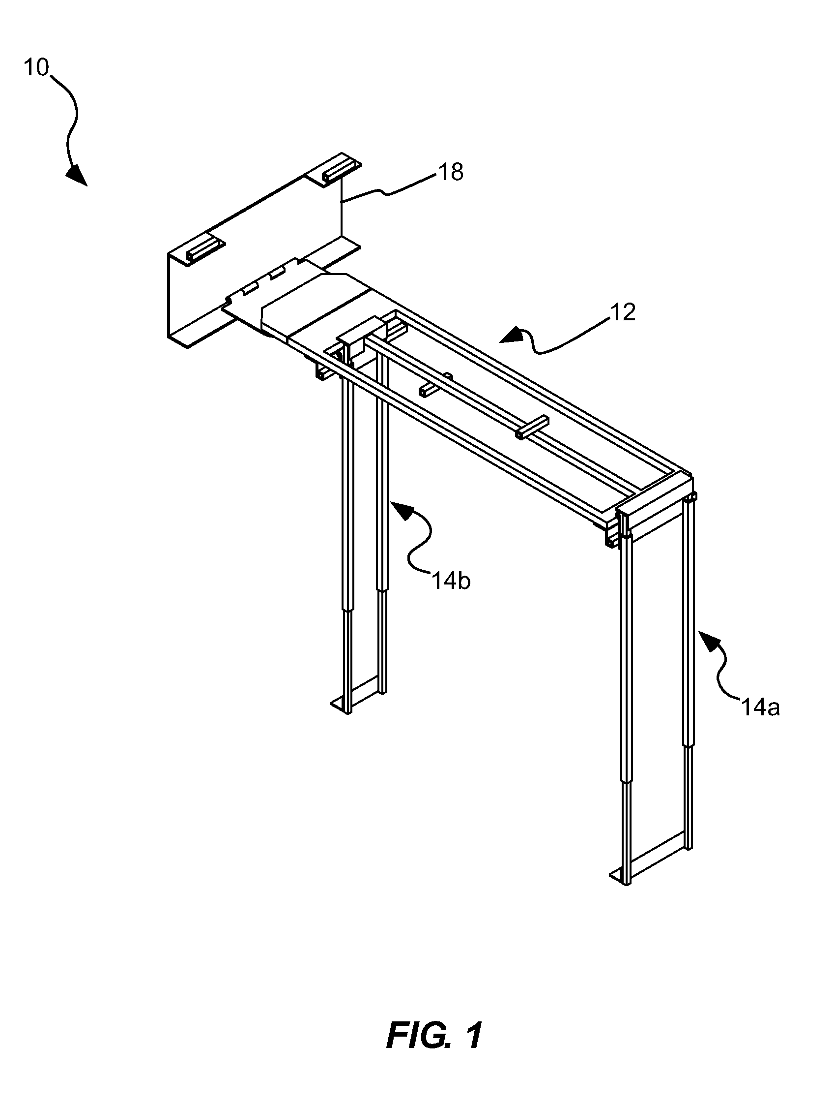
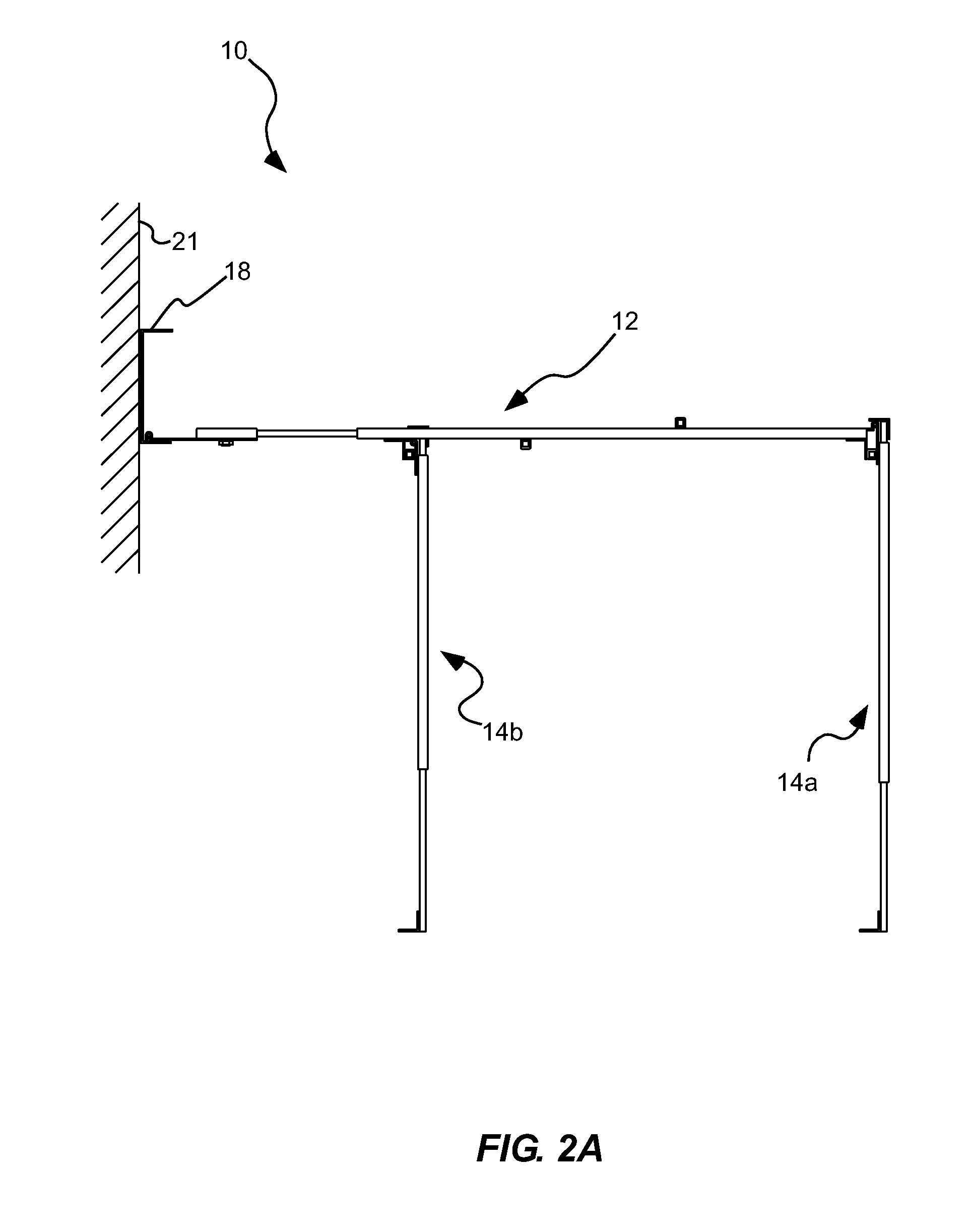
The present invention describes a method for storing saddles on a storage rack. The method involves mounting the rack on a vertical wall, attaching a pivotable storage bed to the mount, rotating the bed to a horizontal position, extending a standalone leg to contact the ground surface, and fixing the leg to support the bed in the horizontal position. This makes it easy to store and access saddles, without needing to manually hold them in place.

Problems solved by technology

While conventional systems abound, most such systems are relatively permanent in nature: once a saddle or the like is removed from the system, the system becomes an obstacle that must be worked around.
However, such systems have proven unstable and often remain a problem when in an unused state.

Method used


Image

  • Retractable Utility Rack
  • Retractable Utility Rack
  • Retractable Utility Rack

Examples


Embodiment Construction

[0025]Reference will now be made to the exemplary embodiments illustrated in the drawings, and specific language will be used herein to describe the same. It will nevertheless be understood that no limitation of the scope of the invention is thereby intended. Alterations and further modifications of the inventive features illustrated herein, and additional applications of the principles of the inventions as illustrated herein, which would occur to one skilled in the relevant art and having possession of this disclosure, are to be considered within the scope of the invention.

[0026]Definitions

[0027]As used herein, the singular forms “a” and “the” can include plural referents unless the context clearly dictates otherwise. Thus, for example, reference to “a voice coil actuator” can include one or more of such actuators.

[0028]As used herein, the terms “attached,”“coupled,” fixed,” etc., can be used to describe a condition in which two or more components are coupled to one another in such...


PUM

PropertyMeasurementUnit
Lengthaaaaaaaaaa
Angleaaaaaaaaaa
Lengthaaaaaaaaaa

Abstract

A utility storage rack comprises a wall mount, mountable to a generally vertical wall, and a storage bed, removably and pivotally coupleable to the wall mount. The storage bed includes at least two components that are adjustable relative to one another to adjust a length of the storage bed. At least one leg is pivotally coupled to the storage bed, the at least one leg being adjustable in length to allow a height or a grade of the storage bed to be adjusted. At least one locking key is removably coupleable with the storage bed, the at least one locking key being coupleable to the storage bed to lock the at least one leg in a downwardly extending orientation, and coupleable to the storage bed to lock the at least one leg in a rotated position, nestable against the storage bed.

Description

BACKGROUND OF THE INVENTION[0001]1. Field of the Invention[0002]The present invention relates generally to the field of utility racks for the storage of various items. More particularly, the present invention relates to collapsible or retractable storage racks that can be retracted to consume a smaller footprint when not in use.[0003]2. Related Art[0004]Numerous utility systems have been developed that allow for the storage of various items in locations where those items are commonly used. For example, saddle racks in a variety of configurations have been developed for the storage of saddles and tack around stalls, horse trailers and the like.[0005]While conventional systems abound, most such systems are relatively permanent in nature: once a saddle or the like is removed from the system, the system becomes an obstacle that must be worked around. Some such systems have been modified to provide a degree of portability. However, such systems have proven unstable and often remain a pro...

Claims


Application Information

Patent Timeline
IPC IPC(8): A47B46/00
CPCA47B46/005A47B5/06A47B81/00B68B9/00B68C1/002Y10T29/49826
Inventor COUCH, GEORGE
Owner COUCH GEORGE
Learn More