Chip card holder for electronic device

Inactive Publication Date: 2014-12-11
SHENZHEN FUTAIHONG PRECISION IND CO LTD +1
View PDF14 Cites 24 Cited by
  • Summary
  • Abstract
  • Description
  • Claims
  • Application Information

AI Technical Summary

Problems solved by technology

Although chip card holders are simple, it can be diffi

Method used


Image

  • Chip card holder for electronic device
  • Chip card holder for electronic device
  • Chip card holder for electronic device

Examples


Embodiment Construction

[0014]The disclosed surface contact card holder can seat chip cards such as SIM cards, compact flash cards (CFs) and multimedia cards (MMCs), for example. The disclosed electronic device in the exemplary embodiment is a mobile phone and can alternatively be a personal digital assistant (PDA), camera, recorder, or other device, while remaining within the scope of the disclosure.

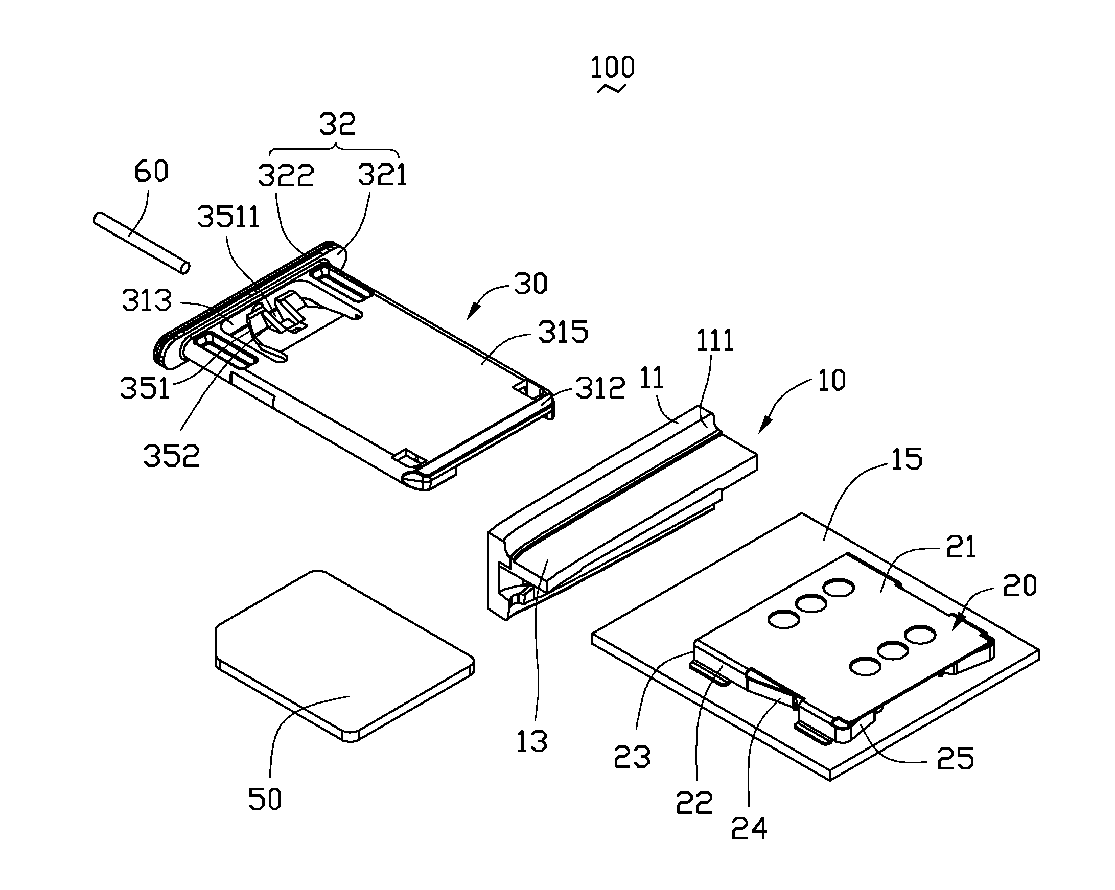
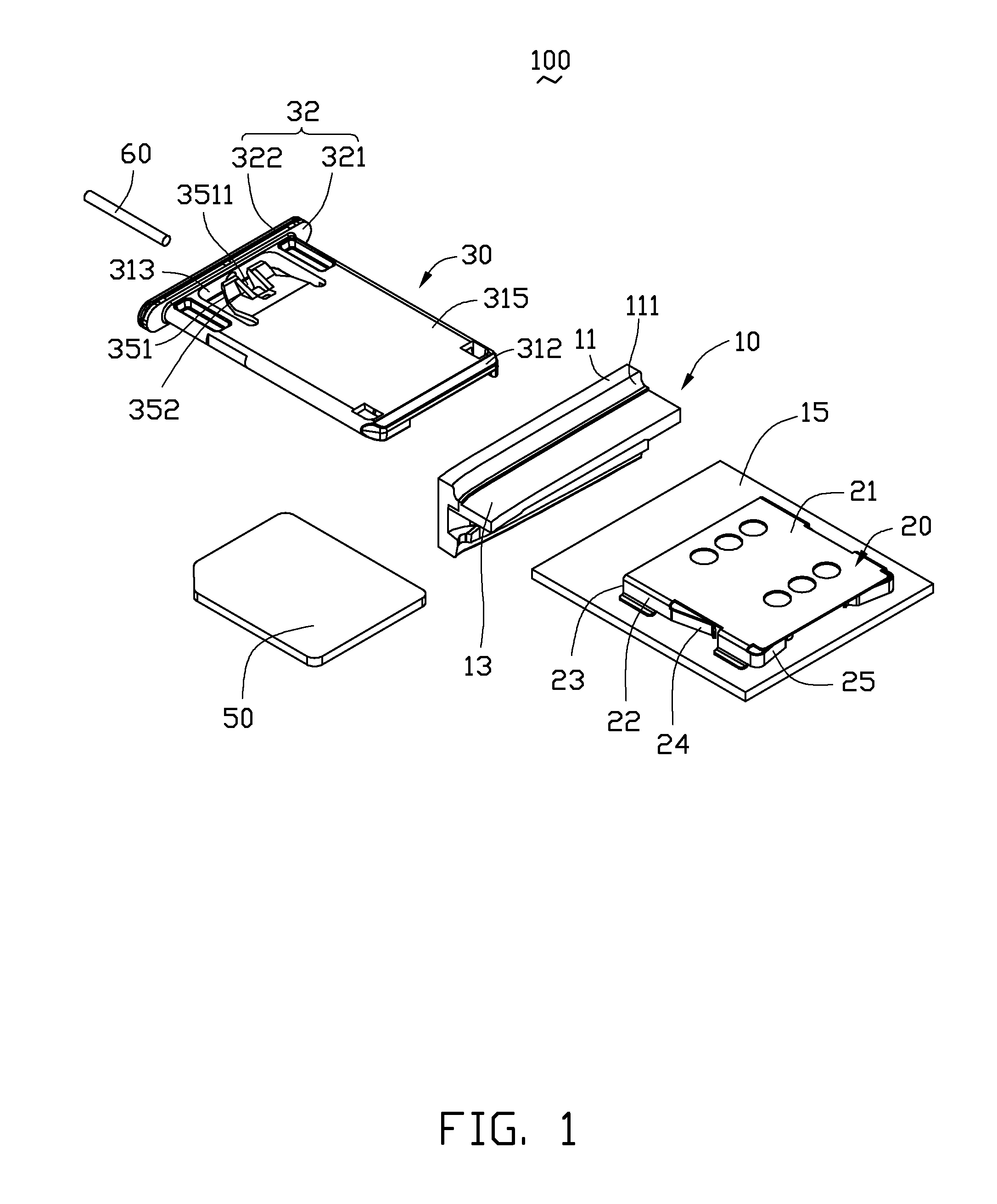
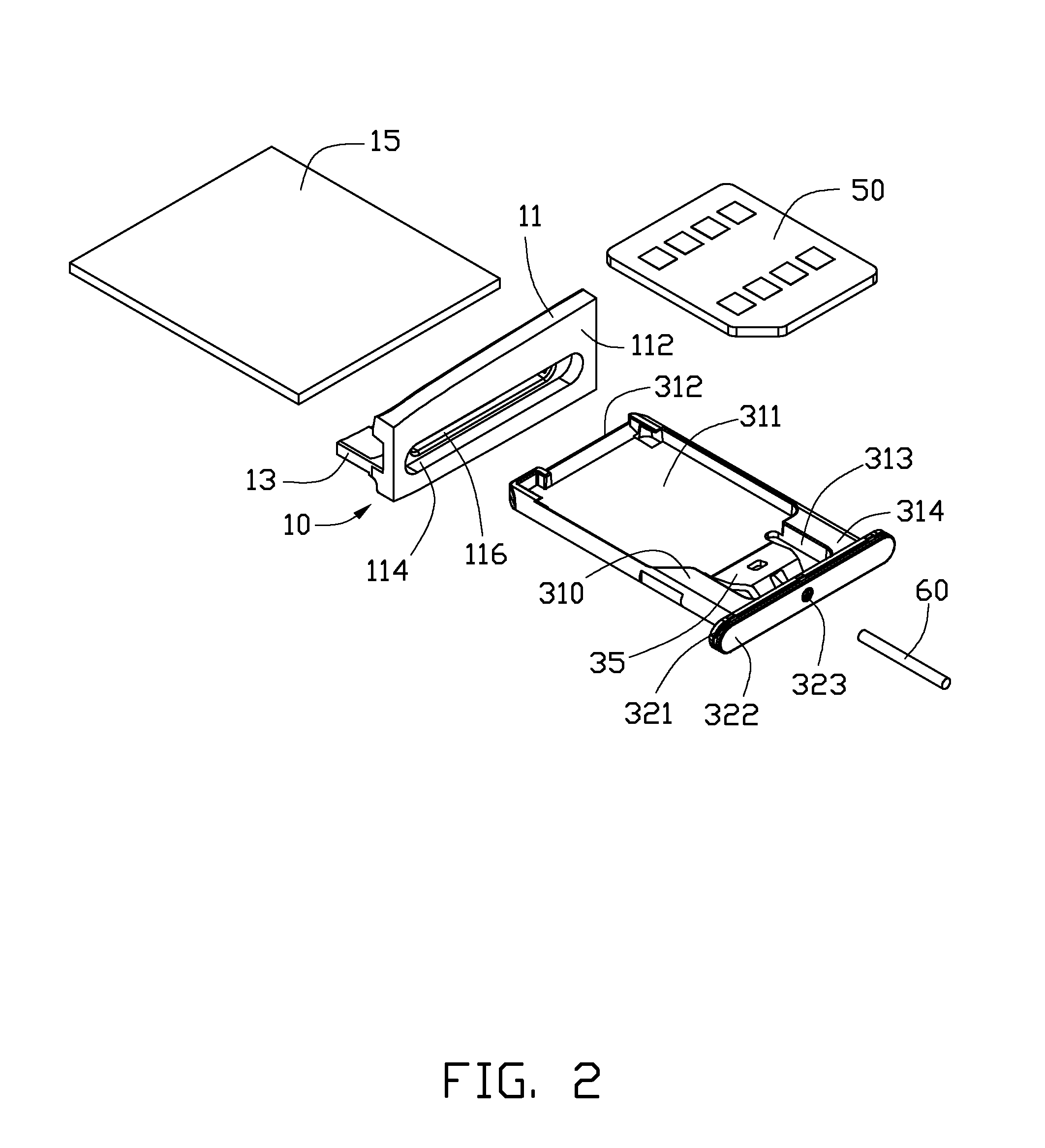
[0015]FIGS. 1 and 2 show a chip card holder 100 for receiving a chip card 50. The chip card holder 100 includes a housing 10, a receiving frame 20, a tray 30, and a pin 60. The tray 30 slidably engages with the receiving frame 20 for latching the chip card 50 in the housing 10. The pin 60 unlocks the tray 30 from the receiving frame 20 to remove the chip card 50.

[0016]The housing 10 may be a portion of the portable electronic device or a separate element fixed to the portable electronic device. In this exemplary embodiment, the housing 10 is a top portion or a bottom portion of the portable electronic device. ...


PUM


Abstract

A chip card holder includes a housing, a receiving frame, a tray, and a pin. The housing defines a latching groove. The receiving frame is mounted to the housing, and the receiving frame includes at least one ejecting arm. The tray is slidably received in the receiving frame and defines a receiving groove configured for receiving a chip card. The tray includes a latching tongue. When the tray is received in the receiving frame, the latching tongue is latched in the latching groove, and the ejecting arm abuts against one end of the tray. The pin deforms the latching tongue to unlock the tray from the housing.

Description

BACKGROUND[0001]1. Technical Field[0002]The present disclosure generally relates to electronic cards of electronic devices, and particularly to a chip card holder for an electronic device.[0003]2. Description of Related Art[0004]With the development of wireless communication and information processing technologies, portable electronic devices such as mobile phones are widely used. Chip cards having special circuits are used in portable electronic devices to enhance or add to the functions of the portable electronic devices.[0005]Although chip card holders are simple, it can be difficult to remove the chip card from the chip card holder.[0006]Therefore, there is room for improvement within the art.BRIEF DESCRIPTION OF THE DRAWINGS[0007]Many aspects of the disclosure can be better understood with reference to the following drawings. The components in the drawings are not necessarily drawn to scale, the emphasis instead being placed upon clearly illustrating the principles of the chip ...

Claims


Application Information

Patent Timeline
IPC IPC(8): H05K5/00H05K5/02G06F1/16
CPCH05K5/0091H05K5/0221H05K5/0086G06F1/16H05K5/026G06K13/0812G06K13/0831G06K13/085G06F1/1658G06K19/077
Inventor LIU, ZHEN-LINQIU, HUI-TAOLIU, WEN-ZE
Owner SHENZHEN FUTAIHONG PRECISION IND CO LTD
Why Eureka
Try Eureka