Supercharge Your Innovation With Domain-Expert AI Agents!

Fluid Holder And Electromechanical Lubricator Employing Same

a technology of electromechanical lubricator and fluid holder, which is applied in the direction of engine lubrication, lubricating pumps, engine components, etc., can solve the problems of increasing friction in the drive assembly, accelerating wear of the drive assembly, and thrusting force along the threaded member against the drive assembly

Active Publication Date: 2014-12-18
STEPHANIA HLDG
View PDF2 Cites 0 Cited by
  • Summary
  • Abstract
  • Description
  • Claims
  • Application Information

AI Technical Summary

Problems solved by technology

However, particularly with viscous fluids, rotation of the threaded member tends to cause pressure to accumulate in the fluid chamber, which results in a thrust force along the threaded member against the drive assembly.
The thrust force exerted by the threaded member against the drive assembly can cause increased friction in the drive assembly.
This increased friction may accelerate wear of the drive assembly, for example by causing misalignment of gears in the drive assembly, which may result in reduced life span for the drive assembly.
The increased friction also requires delivery of more power by the drive assembly, thereby shortening the life span of batteries or other power sources for the drive assembly.
The increased friction from the thrust force on the drive assembly may also limit the pressure that the drive assembly can exert on the fluid, and may limit the temperature range in which the lubricator can operate.
Also, an accumulation of thrust force on the threaded member can cause the drive assembly of the lubricator to separate from the lubricator, and this potential for a significant accumulation of thrust force on the threaded member can cause disassembly of the lubricator to be difficult or unsafe.

Method used


Image

  • Fluid Holder And Electromechanical Lubricator Employing Same
  • Fluid Holder And Electromechanical Lubricator Employing Same
  • Fluid Holder And Electromechanical Lubricator Employing Same

Examples


first embodiment

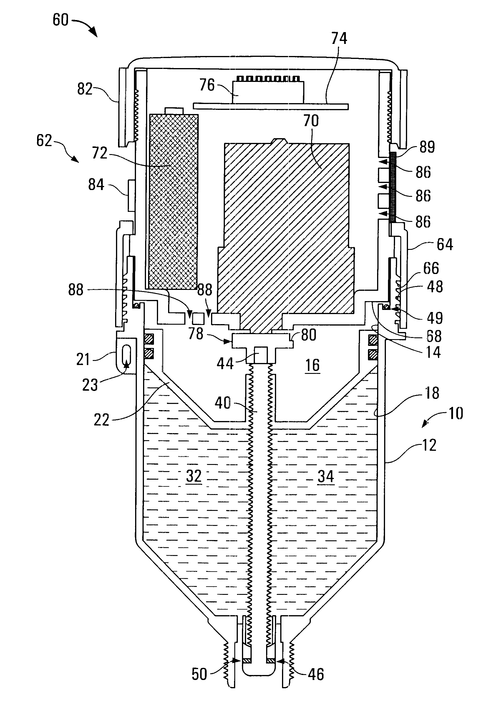
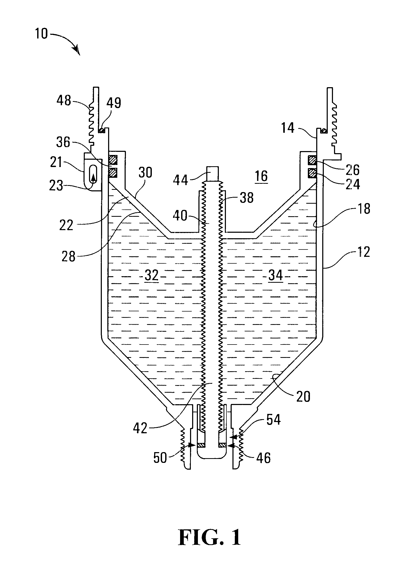
[0027]Referring to FIG. 1, a fluid holder according to the invention is shown generally at 10. The fluid holder 10 includes a housing 12 having an inner surface 14 that defines a cavity 16. In the illustrated embodiment, the inner surface 14 includes a cylindrically shaped sliding portion 18 and a generally frustoconical terminating portion 20. Alternatively, the terminating portion of inner surface 14 may be conical, for example. Housing 12 preferably includes a tie-down 21 defining an eyelet 23, and the eyelet 23 may receive a cord to facilitate attaching fluid holder 10 to an object (not shown), for example. However, it will be appreciated that equivalent results can be achieved with other configurations of the housing 12.

[0028]A piston 22 is positioned in cavity 16 in slidable engagement with sliding portion 18 of the inner surface 14. Piston 22 preferably includes sealing members such as O-rings 24 and 26 to facilitate slidable and sealed engagement with the inner surface 14. P...

second embodiment

[0033]Referring to FIG. 3, a fluid holder according to the invention is shown generally at 90. Fluid holder 90 includes a housing 92 having an inner surface 94 that defines a cavity 96. In the illustrated embodiment, the inner surface 94 includes a cylindrically shaped sliding portion 98 and a frustoconically shaped terminating portion 100 that includes a generally flat surface 102. Housing 92 preferably includes a tie-down 91 defining an eyelet 93, and the eyelet 93 may receive a cord to facilitate attaching fluid holder 90 to an object (not shown), for example.

[0034]The fluid holder 90 further includes a piston 104 positioned in cavity 96 in slidable engagement with sliding portion 98 of inner surface 94. Piston 104 includes a first surface 106 and a second opposite surface 108, and is positioned in cavity 96 such that first surface 106 and inner surface 94 define a fluid chamber 110 in cavity 96 for holding a fluid such as a lubricant 112, for example. First surface 106 of piston...


PUM


Abstract

A fluid holder includes: a housing having an inner surface and at least one fluid outlet; a piston in slidable engagement with the inner surface and having first and second opposed surfaces with a threaded opening extending therebetween, the first surface of the piston and the inner surface of the housing defining a fluid chamber in communication with the at least one fluid outlet; and a threaded member engageable with the threaded opening, a first portion of the threaded member extending from the first surface of the piston, the threaded member being rotatably coupled to the housing on the first portion of the threaded member for rotation in the threaded opening of the piston such that rotation of the threaded member causes a force to be exerted by the threaded member on the housing and on the piston to expand or contract the fluid chamber.

Description

BACKGROUND OF THE INVENTION[0001]1. Field of Invention[0002]The invention relates generally to lubrication, and more particularly to a fluid holder and an electromechanical lubricator employing the same.[0003]2. Description of Related Art[0004]Known electromechanical lubricators include fluid holders that are detachably coupled to drive assemblies. In known electromechanical lubricators, the drive assembly causes rotation of a threaded member that is threaded through a threaded piston, urging the threaded piston in a direction that tends to expel fluid out of a fluid chamber through a fluid outlet. However, particularly with viscous fluids, rotation of the threaded member tends to cause pressure to accumulate in the fluid chamber, which results in a thrust force along the threaded member against the drive assembly.[0005]The thrust force exerted by the threaded member against the drive assembly can cause increased friction in the drive assembly. This increased friction may accelerate...

Claims


Application Information

Patent Timeline
Patent Type & Authority Applications(United States)
IPC IPC(8): F16N11/08
CPCF16N11/08
Inventor ORLITZKY, STEPHAN KARLSHEREMETA, DANIEL JOSEPH
Owner STEPHANIA HLDG
Features
  • R&D
  • Intellectual Property
  • Life Sciences
  • Materials
  • Tech Scout
  • Unparalleled Data Quality
  • Higher Quality Content
  • 60% Fewer Hallucinations
Learn More