
Eea anvil snap ring activator

a technology of snap ring and anvil head, which is applied in the field of surgical fastening devices, can solve the problems of tissue surrounding the point of connection the anvil rod, and may interfere with the pivoting or tilting of the anvil head with respect to the anvil rod,

Active Publication Date: 2014-12-18
TYCO HEALTHCARE GRP LP
View PDF8 Cites 27 Cited by
  • Summary
  • Abstract
  • Description
  • Claims
  • Application Information

AI Technical Summary

Benefits of technology

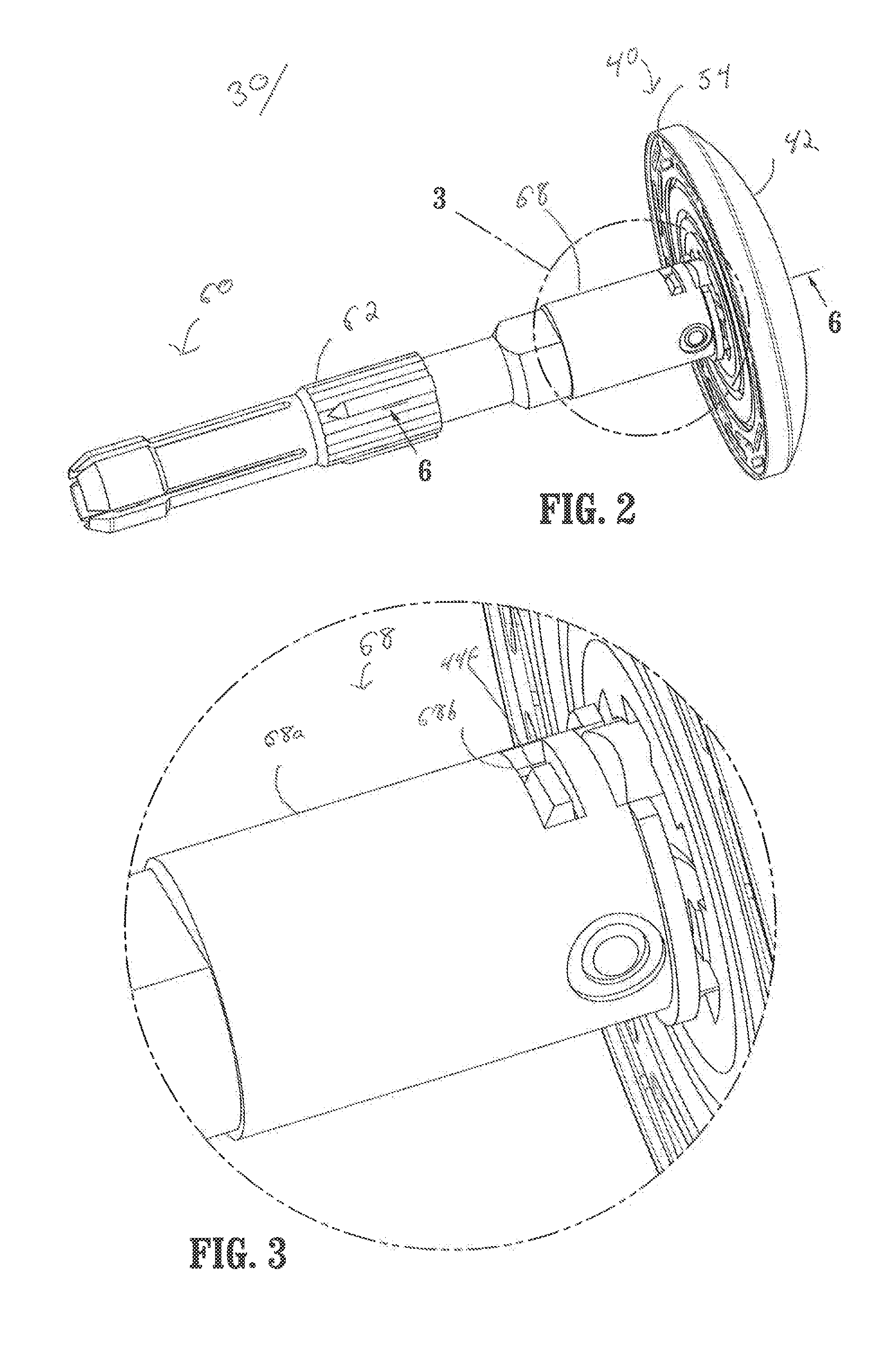
The present disclosure is about a surgical fastening apparatus that includes a handle assembly, a central body portion, and a distal head portion. The distal head portion has an anvil head assembly and an anvil center rod assembly. The anvil head assembly has an activator plate, a deformable member, and a securing member. The deformable member is positioned between the activator plate and the anvil center rod assembly. The anvil center rod assembly has a plunger that is in mechanical communication with the anvil head assembly. The deformable member is designed to deform when the surgical fastening apparatus is actuated, causing the activator plate to move distally into the interior recess of the anvil head assembly. The anvil head assembly also has a post that defines an annular groove for securely receiving the securing member. The deformable member may include a body and an extension that deforms with respect to the body. The anvil center rod assembly has a ridge that inhibits the anvil head from pivoting about the pivot axis. The anvil center rod assembly also includes a sleeve that engages tissue and slides proximally upon pivoting of the anvil head assembly. The method of using the surgical fastening apparatus involves actuating it to cause the annular knife to contact the cut ring in the anvil head assembly, advancing the annular knife to move the activation plate and deform the deformable member, and securing the activation plate with the securing ring to pivot the anvil head assembly. The method may also involve creating a smaller cross-sectional profile of the surgical fastening apparatus.

Problems solved by technology

However, given the close tolerances of the movable components of such a surgical fastening device, various movable components may interfere with the pivoting or tilting of the anvil head with respect to the anvil rod.
Further, tissue surrounding the point of connection of the anvil head and anvil rod may interfere with the pivoting or tilting of the anvil head with respect to the anvil rod.

Method used


Image

  • Eea anvil snap ring activator
  • Eea anvil snap ring activator
  • Eea anvil snap ring activator

Examples


Embodiment Construction

[0036]With reference now to the drawings wherein like numerals represent like elements throughout the several views, the presently-disclosed surgical fastening apparatus will be described. As used herein, the term “operator” may refer to any user, e.g., a nurse, doctor, or clinician, of the presently-disclosed surgical fastening apparatus. Further, the term “distal” refers to that portion of the surgical fastening apparatus, or component thereof, further from the operator while the term “proximal” refers to that portion of the surgical fastening apparatus, or component thereof, closer to the operator.

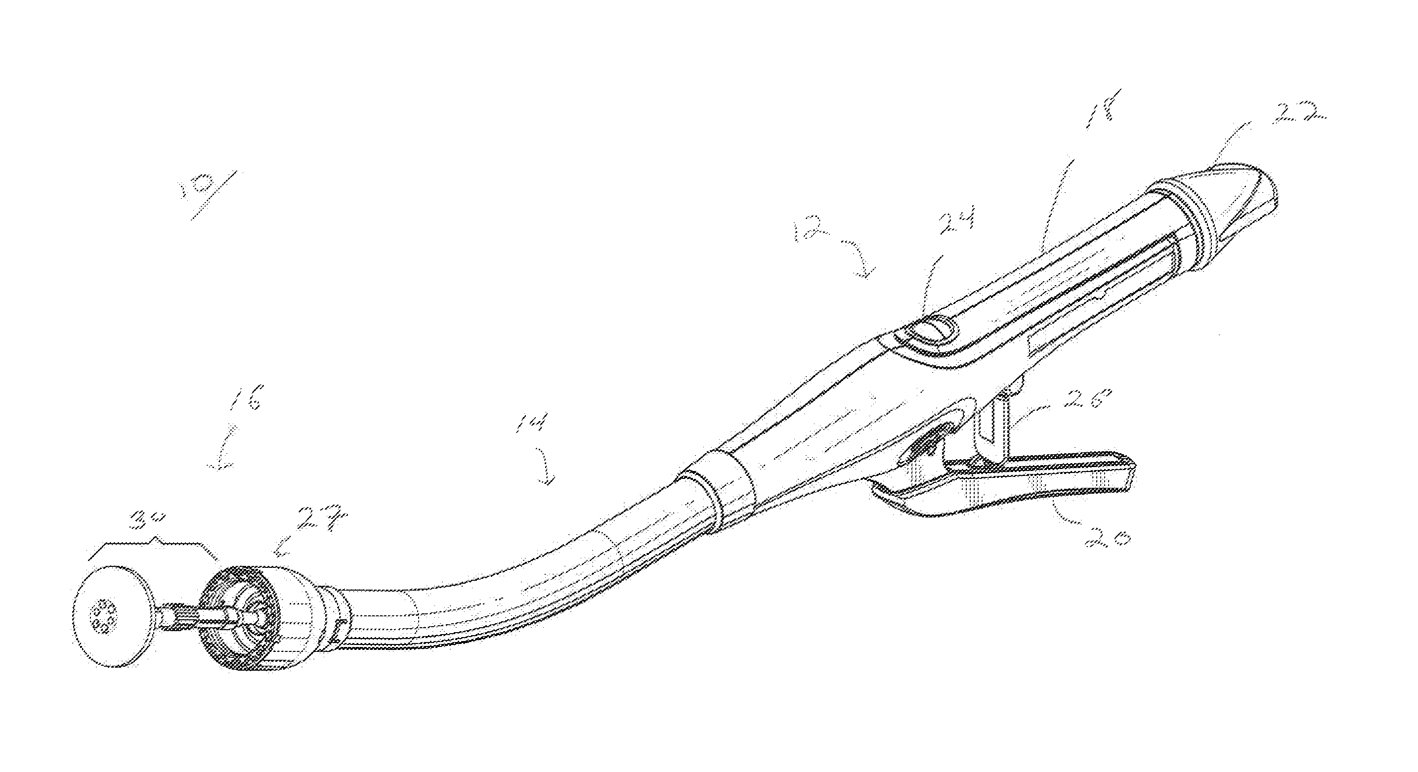
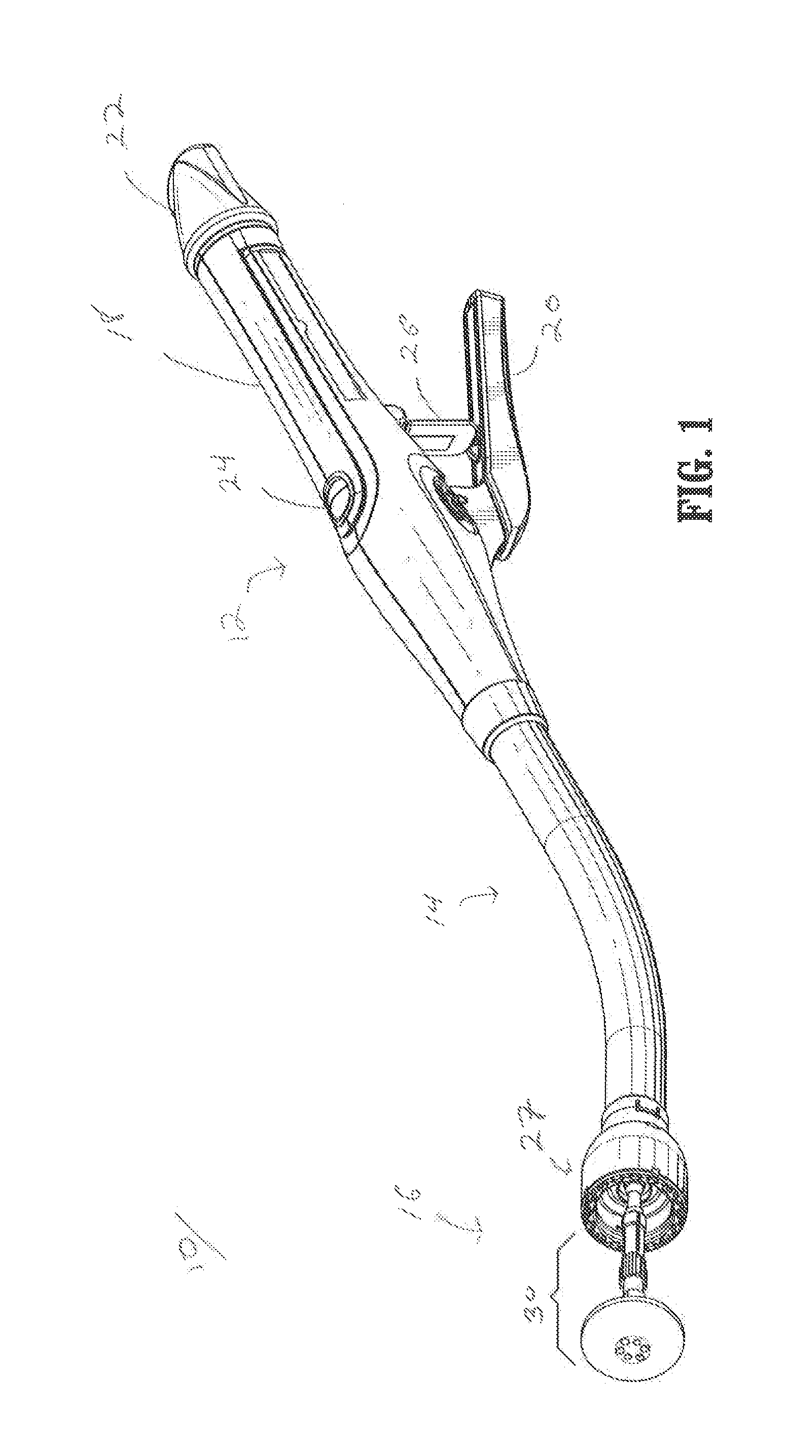
[0037]Referring initially to FIG. 1, an embodiment of the presently disclosed surgical fastening apparatus is illustrated generally as 10. Briefly, surgical fastening apparatus 10 includes a proximal handle assembly 12, an elongated central body portion 14 including a curved elongated outer tube 14a, and a distal head portion 16. Distal head potion 16 includes a shell assembly 27 and an...


PUM

PropertyMeasurementUnit
areaaaaaaaaaaa
lengthaaaaaaaaaa
shapeaaaaaaaaaa

Abstract

A surgical fastening apparatus and associated method of use is disclosed. The surgical fastening apparatus includes a handle assembly, a central body portion extending from the handle assembly, and a distal head portion including an anvil head assembly. The anvil head assembly includes an anvil head defining an interior recess, an activator plate, a deformable member, and a securing member. The anvil center rod assembly defines a longitudinal axis and is pivotably connected to the anvil head assembly about a pivot axis. The anvil center rod assembly includes a configured to contact the anvil head assembly upon an actuation of the surgical fastening apparatus. Upon the actuation of the surgical fastening apparatus, the deformable member is configured to deform such that the activator plate is advanced distally into the interior recess to facilitate the anvil head pivoting about the pivot axis.

Description

BACKGROUND[0001]1. Technical Field[0002]The present disclosure relates generally to a surgical fastening device for applying surgical fasteners to body tissue. More particularly, the present disclosure relates to a surgical fastening device suitable for performing circular anastomosis and / or treatment to internal walls of hollow tissue organs.[0003]2. Background of Related Art[0004]Anastomosis is the surgical joining of separate hollow organ sections. Typically, an anastomosis procedure follows surgery in which a diseased or defective section of hollow tissue is removed and the remaining end sections are to be joined. Depending on the desired anastomosis procedure, the end sections may be joined by either circular, end-to-end or side-to-side organ reconstruction methods.[0005]In a circular anastomosis procedure, the two ends of the organ sections are joined by means of a fastener instrument which drives a circular array of fasteners, e.g., staples, through the end section of each or...

Claims


Application Information

Patent Timeline
Patent Type & Authority Applications(United States)
IPC IPC(8): A61B17/068
CPCA61B17/068A61B17/115A61B2017/0725A61B2017/07257A61B17/1155
Inventor WILLIAMS, JUSTIN
Owner TYCO HEALTHCARE GRP LP
Learn More