Motion analysis method and motion analysis device

a motion analysis and motion analysis technology, applied in the field of motion analysis methods and motion analysis devices, can solve the problems of large discrepancy, time-consuming to display the swing plane, similar problems

Inactive Publication Date: 2014-12-25
SEIKO EPSON CORP
View PDF2 Cites 64 Cited by
  • Summary
  • Abstract
  • Description
  • Claims
  • Application Information

AI Technical Summary

Benefits of technology

[0007]An advantage of some aspect of the invention is that a motion analysis method and a motion analysis device are provided which are capable of presenting a clear indicator in analyzing the motion of a swing.
[0009]To establish the static posture of the sporting gear, the subject reproduces the posture at the moment of impact. As a result, the posture at the moment of impact is extracted from a series of movements called “swing”. The inertial sensor outputs a detection signal according to the posture of the sporting gear. The first imaginary plane is specified according to the detection signal. The first imaginary plane can depict an imaginary trajectory of the sporting gear swung in the swing. The trajectory of the sporting gear in the swing is observed in comparison with the imaginary trajectory. The movement of the subject is analyzed, based on the trajectory of the sporting gear. Thus, a clear indicator is provided with respect to the motion “swing”. According to this configuration, in the case of a golf swing, the first imaginary plane can be regarded as the shaft plane, and for example, based on the inclination of the shaft plane when the subject is at address position, the subject can grasp the difference in the distance between the subject and the ball and the difference in the posture of the subject and can thoroughly examine the causes of good or bad ball hitting.
[0011]According to this configuration, an acceleration sensor is used as the inertial sensor. Based on the output from the acceleration sensor in the static posture, for example, how much the shaft of the golf club is inclined with respect to the direction of gravity can be found. Using the inclination information and the length information of the shaft, the shaft plane can be easily specified.
[0014]According to this configuration, the second imaginary plane can be regarded as the Hogan plane, and for example, based on the inclination of the Hogan plane when the subject is at address position, the subject can grasp the difference in the distance between the subject and the ball and the difference in the posture of the subject and can thoroughly examine the causes of good or bad ball hitting.
[0016]According to this configuration, an acceleration sensor is used as the inertial sensor. Based on the output from the acceleration sensor in the static posture, for example, how much the direction in which the subject's arm extends is inclined with respect to the direction of gravity can be found. Using the inclination information and the length information of the arm, the position of the subject's shoulder can be specified and the Hogan plane can be easily specified.
[0019]According to this configuration, for example, in the case of a golf swing, the first imaginary plane can be regarded as the shaft plane, and the second imaginary plane can be regarded as the Hogan plane. Then, for example, based on the inclination of the Hogan plane when the subject is at address position, the subject can grasp the difference in the distance between the subject and the ball and the difference in the posture of the subject and can thoroughly examine the causes of good or bad ball hitting.

Problems solved by technology

Therefore, there is a problem that a large discrepancy from the actual swing plane is generated and also a problem that it is time-consuming to display the swing plane.
The technique of JP-A-2008-23036, too, requires some work to edit image data and therefore has similar problems to those of JP-A-2009-20897.
Therefore, there are no previous measures to present the shaft plane and the Hogan plane easily and accurately to the golfer in golf swing analysis.

Method used


Image

  • Motion analysis method and motion analysis device
  • Motion analysis method and motion analysis device
  • Motion analysis method and motion analysis device

Examples


first embodiment

1. Configuration of Golf Swing Analysis Device

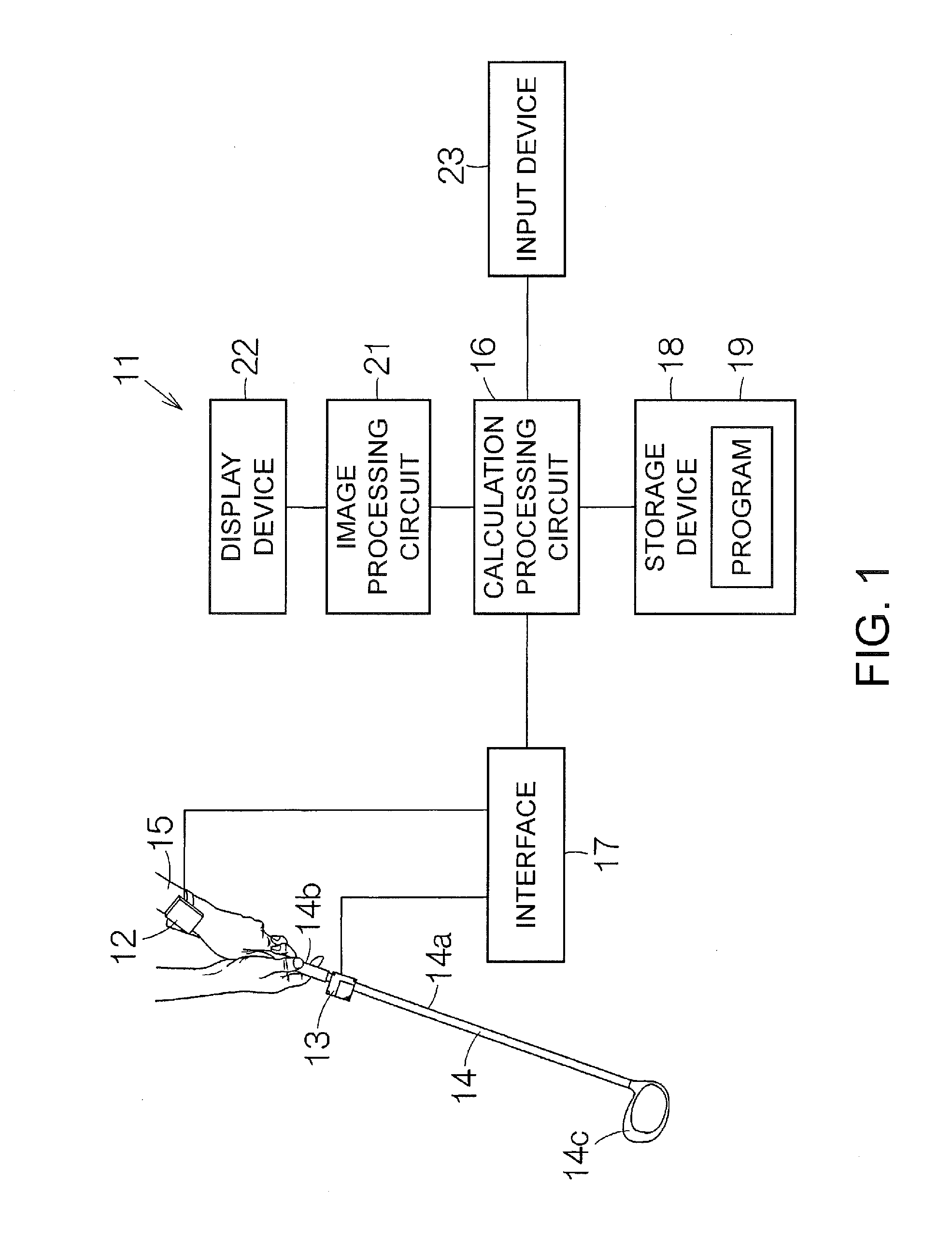
[0041]FIG. 1 schematically shows the configuration of a golf swing analysis device (motion analysis device) 11 according to a first embodiment of the invention. The golf swing analysis device 11 has, for example, a first inertial sensor 12 and a second inertial sensor 13. An acceleration sensor and a gyro sensor are incorporated in the first and second inertial sensors 12, 13. The acceleration sensor can detect each one of accelerations generated in three axial directions that are orthogonal to each other. The gyro sensor can detect each one of angular velocities about each of the three orthogonal axes. The first and second inertial sensors 12, 13 output a detection signal. Based on the detection signal, the acceleration and angular velocity are specified for each axis. The acceleration sensor and the gyro sensor detect information of acceleration and angular velocity. The first inertial sensor 12 is mounted on a golfer's upper limb (for...

second embodiment

5. Configuration of Golf Swing Analysis

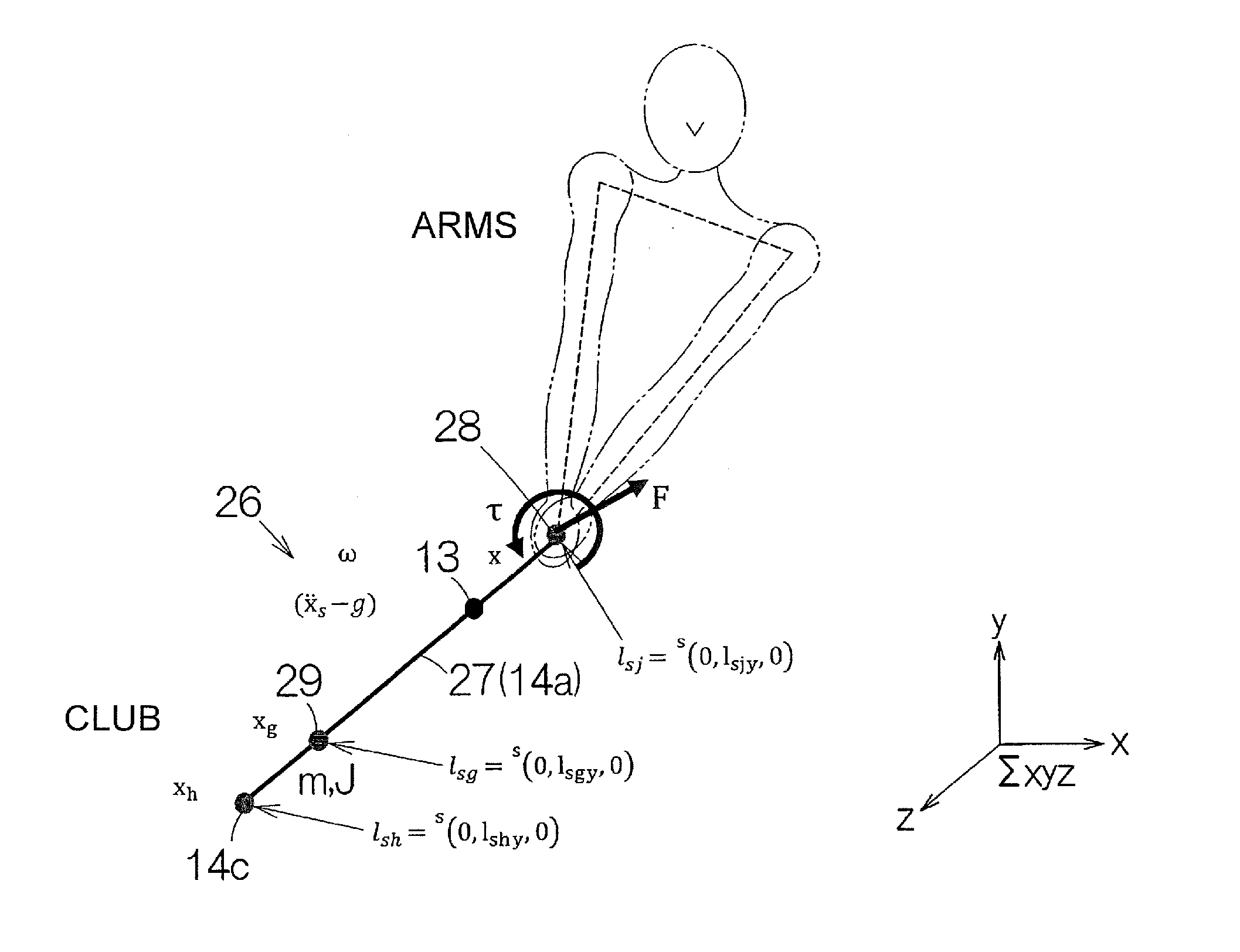
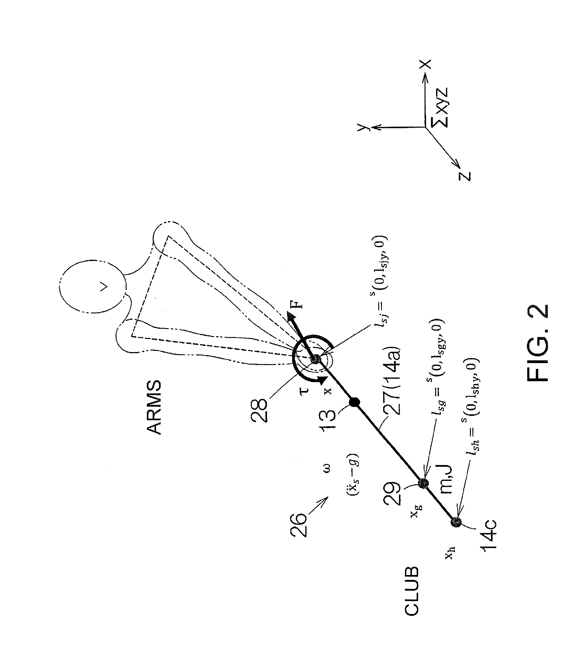
[0074]FIG. 11 schematically shows the configuration of a golf swing analysis device 11a according to a second embodiment. In this golf swing analysis device 11a, compared with the golf swing analysis device 11 according to the first embodiment, the first inertial sensor 12 is omitted. That is, a single inertial sensor, that is, the second inertial sensor 13 is used in the analysis of a golf swing. A calculation processing circuit 16a replaces the calculation processing circuit 16 according to the first embodiment. A position calculation unit 51a may calculate the coordinates of the club head 14c and the coordinates of the grip end, according to the absolute reference coordinates in the imaginary three-dimensional space. A swing movement calculation unit 54a may calculate the displacement of the subject's arm or the club head, according to the absolute reference coordinates.

[0075]As shown in FIG. 12, the shaft plane image data generation unit 52...


PUM


Abstract

A motion analysis device includes a calculation unit which specifies a first imaginary plane, that is, a shaft plane formed by a first line segment representing a direction in which a shaft part of a sporting gear in a static posture extends and a second line segment representing a ball hitting direction, with the use of an output from an inertial sensor.

Description

BACKGROUND[0001]1. Technical Field[0002]The present invention relates to a motion analysis method and a motion analysis device.[0003]2. Related Art[0004]For example, in golf, which is a specific example of sports, the concept of the swing plane is commonly known. The swing plane is equivalent to the trajectory of the golf club when swung. For example, according to JP-A-2009-20897 and JP-A-2008-23036, a golf swing made by a subject is shot with a camera from behind the subject and the swing plane is specified based on the shot image.[0005]The technique for finding the swing plane according to JP-A-2009-20897 is to find at least two specific points in the swing from image data and analyze the swing plane based on the two points. In this technique, first, after the swing is finished, it is necessary to edit the image data and carry out work to find specific points. Therefore, there is a problem that a large discrepancy from the actual swing plane is generated and also a problem that it...

Claims


Application Information

Patent Timeline
Patent Type & Authority Applications(United States)
IPC IPC(8): A63B24/00A63B71/06G01P15/02A63B69/36
CPCA63B24/0006A63B69/36A63B71/0619G01P15/02A63B2220/51A63B2220/833A63B2220/836A63B2220/40A63B2071/0647G09B19/003A61B5/6895A61B5/744A61B5/1122A61B2562/0219A63B69/3608A63B24/0003A63B2220/18A63B2220/803A63B2208/0204
Inventor SATO, MASAFUMI
Owner SEIKO EPSON CORP
Why Eureka
Try Eureka