
Display device switchable between mirror mode and display mode

a display device and mirror mode technology, applied in non-linear optics, instruments, optics, etc., can solve the problems of unfavorable vision quality and inability of users to configure the panel, and achieve the effect of improving the interference between the mirror image and the display imag

Active Publication Date: 2015-02-05
AU OPTRONICS CORP
View PDF6 Cites 8 Cited by
  • Summary
  • Abstract
  • Description
  • Claims
  • Application Information

AI Technical Summary

Benefits of technology

The technical effect of this patent is to improve the interference between a mirror image and a display image by providing a display device that can switch between a mirror mode and a display mode. Additionally, the display area can be configured into multiple display regions, with some regions in the mirror mode and others in the display mode.

Problems solved by technology

For this conventional technology, the mirror image and the display image are easily interfered with each other so that the vision quality is unfavorably affected.
Besides, for this conventional technology, it is not possible for the user to configure the panel to exhibit the mirror image in some regions and simultaneously to exhibit the display image in other regions.

Method used


Image

  • Display device switchable between mirror mode and display mode
  • Display device switchable between mirror mode and display mode
  • Display device switchable between mirror mode and display mode

Examples


Embodiment Construction

[0034]Reference will now be made in detail to the present embodiments of the present disclosure, examples of which are illustrated in the accompanying drawings. The example is not the only way to implement or utilize the present disclosure. The embodiments disclosed below may be combined or replaced each other in some better way. These combinations may not be described or explained further. Wherever possible, the same reference numbers are used in the drawings and the description to refer to the same or like parts.

[0035]Specific examples of components and arrangements are described below to simplify the present disclosure. These are, of course, merely examples and are not intended to be limiting. In order to simplify the drawing, some well-known structure and device may be illustrated in the Figures schematically.

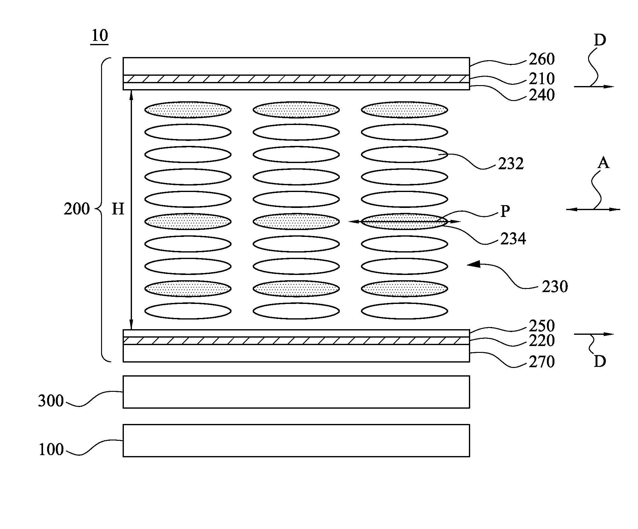
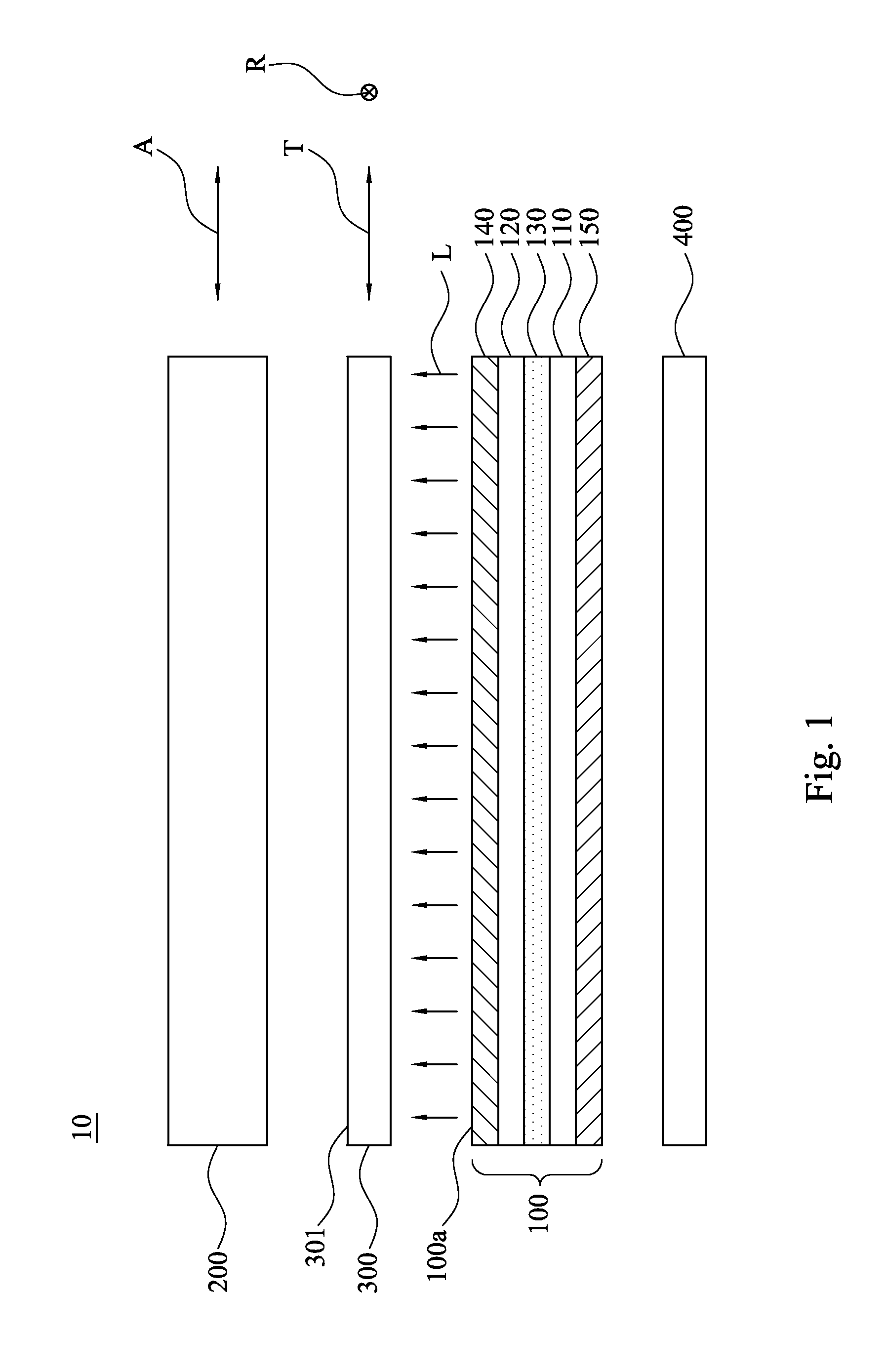
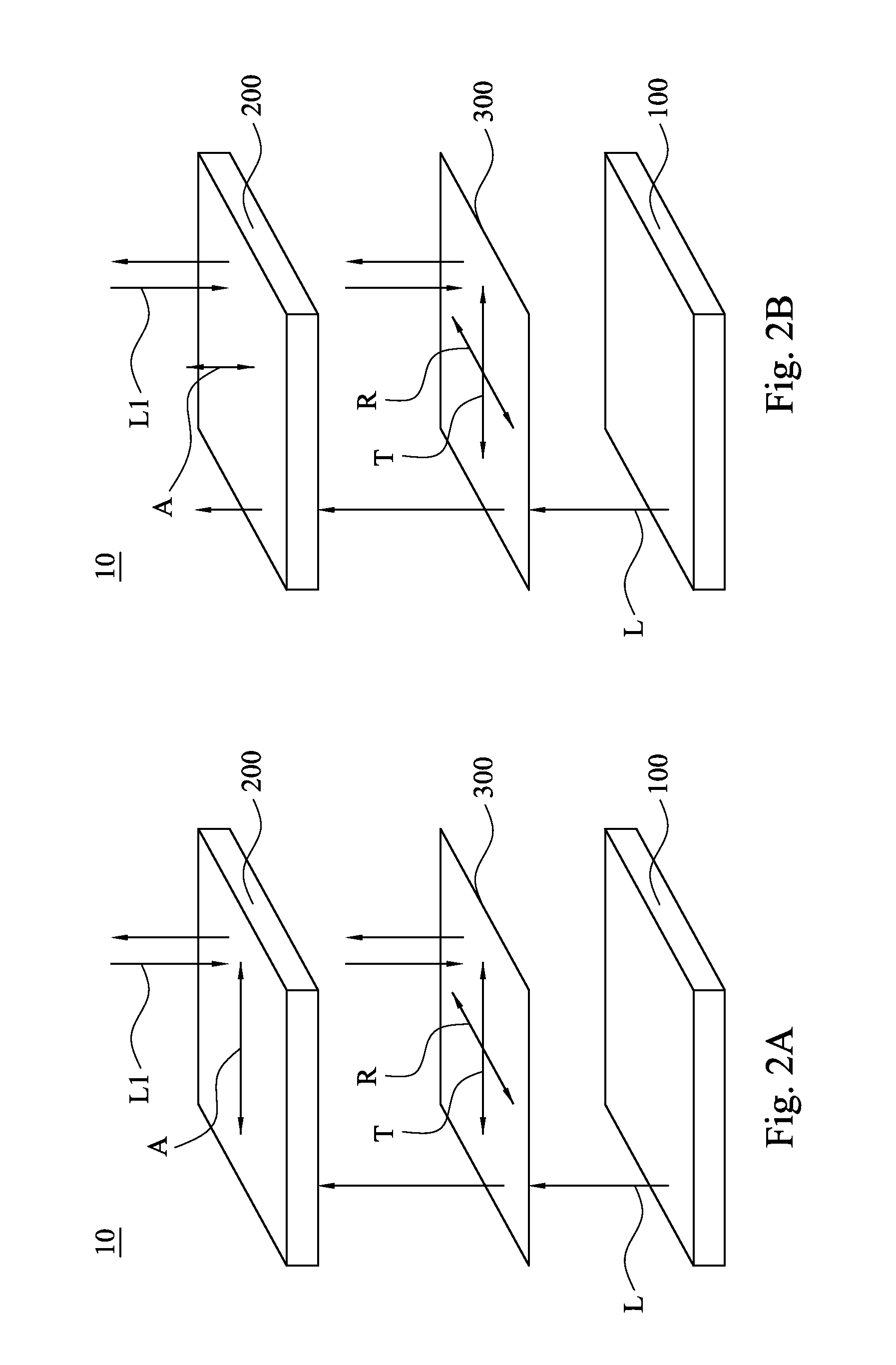
[0036]On aspect of the present disclosure is to provide a display device switchable between a mirror mode and a display mode. In specifics, the display device has two opera...


PUM

PropertyMeasurementUnit
thicknessaaaaaaaaaa
thicknessaaaaaaaaaa
thicknessaaaaaaaaaa

Abstract

Disclosed herein is a display device switchable between a mirror mode and a display mode. The display device includes a display panel, a polarizing element and a reflective polarizer. The display panel has a light-emitting surface for emitting a polarized light. The polarizing element has an absorption axis, and is disposed on a side adjacent to the light-emitting surface. The polarizing element is switchable between a polarizing mode and a non-polarizing mode. When the polarizing element is operated in the polarizing mode, the polarizing element absorbs a polarized light in the polarization direction parallel with the absorption axis. When the polarizing element is operated in the non-polarizing mode, the polarizing element allows the polarized light emitted from the display panel to pass there through. The reflective polarizer is disposed between the display panel and the polarizing element.

Description

RELATED APPLICATIONS[0001]This application claims priority to Taiwan Application Serial Number 102127802, filed Aug. 2, 2013, the entity of which is incorporated herein by reference.BACKGROUND[0002]1. Technical Field[0003]The present disclosure relates to a display device. More particularly, the present disclosure relates to a display device which is switchable between a mirror mode and a display mode.[0004]2. Description of Related Art[0005]With the development of flat panel display application, the display with switchable mirror function is demanded. Generally, the display with switchable mirror function means a display which possesses both display function and mirror function. In the prior art, the display with mirror function is implemented by adding a reflective polarizer. For this conventional technology, the mirror image and the display image are easily interfered with each other so that the vision quality is unfavorably affected. Besides, for this conventional technology, it...

Claims


Application Information

Patent Timeline
Patent Type & Authority Applications(United States)
IPC IPC(8): G02F1/1335
CPCG02F1/133536G02F1/13725G02F2203/01G02F2203/02
Inventor CHEN, KUEI-BAILI, CHIA-HAOLIAO, CHEN-HSIENHSUEH, CHIH-LING
Owner AU OPTRONICS CORP
Learn More