Key structure

a key structure and key technology, applied in the field of key structures, can solve problems such as drawbacks, difficulty for users to disassemble key structures, and replace elastic rubbery elements,

Inactive Publication Date: 2015-02-19
PRIMAX ELECTRONICS LTD
View PDF4 Cites 22 Cited by
  • Summary
  • Abstract
  • Description
  • Claims
  • Application Information

AI Technical Summary

Problems solved by technology

However, since the elastic rubbery element 13 is made of a rubbery material, some drawbacks may occur.
As kn

Method used


Image

  • Key structure
  • Key structure
  • Key structure

Examples


first embodiment

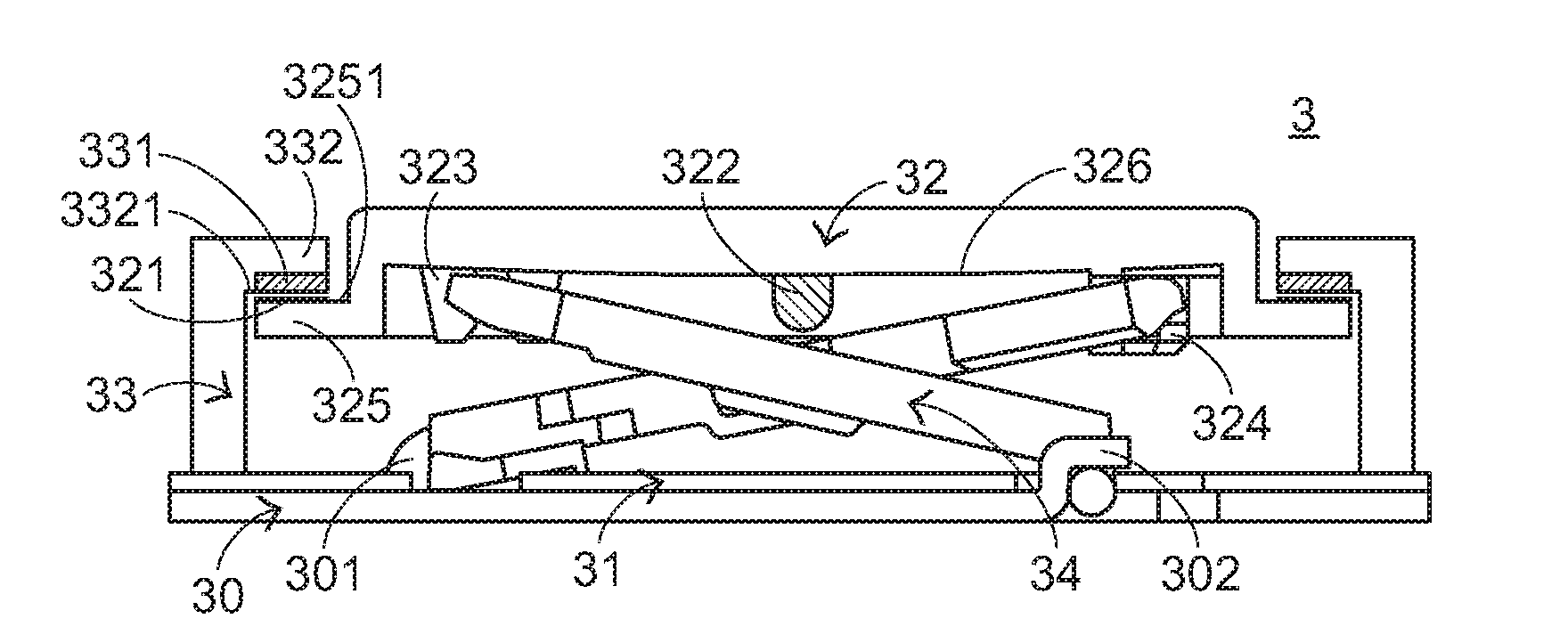
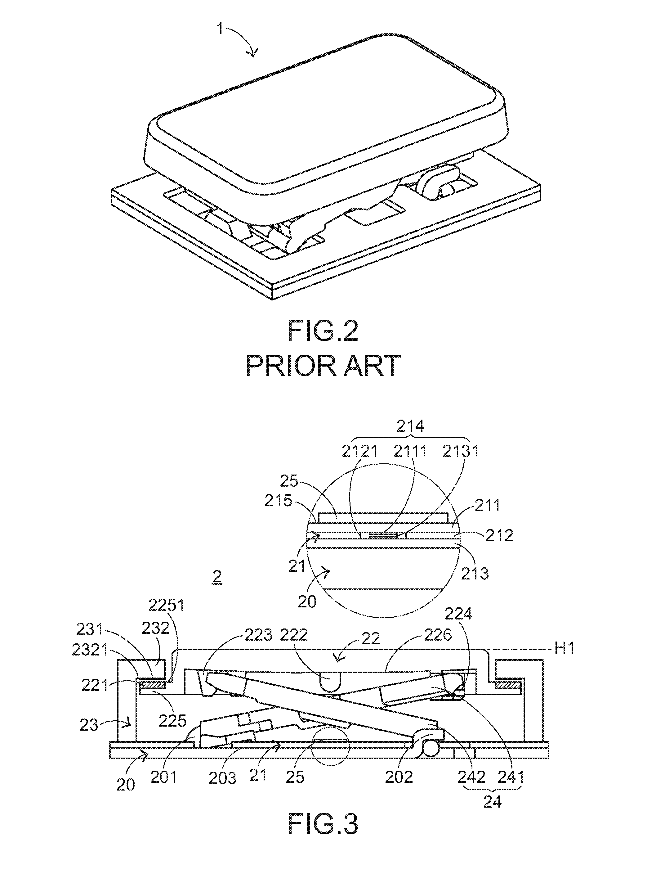
[0020]FIG. 3 is a schematic side view illustrating a key structure according to the present invention. As shown in FIG. 3, the key structure 2 comprises a base plate 20, a switch circuit board 21, a keycap 22, an enclosure frame 23, a connecting member 24, and a cushioning element 25. The base plate 20 is connected with the connecting member 24. In addition, the base plate 20 comprises a first fixing structure 201 and a second fixing structure 202. The first fixing structure 201 and the second fixing structure 202 are disposed on a top surface 203 of the base plate 20. The switch circuit board 21 is disposed on the base plate 20. When the switch circuit board 21 is triggered by the keycap 22, the switch circuit board 21 generates a corresponding key signal. In this embodiment, the switch circuit board 21 comprises an upper wiring board 211, a spacer layer 212, and a lower wiring board 213. The upper wiring board 211 has an upper contact 2111. The spacer layer 212 is disposed under t...

third embodiment

[0031]Please refer to FIGS. 6 and 7. FIG. 7 is a schematic perspective view illustrating the key structure according to the present invention and taken along another viewpoint. The keycap 42 is supported by the enclosure frame 43, and disposed over the switch circuit board 41. When the keycap 42 is depressed, the keycap 42 is moved downwardly to trigger the switch circuit board 41. The keycap 42 comprises plural magnetic coating layers 421, a triggering part 422, and plural inclined protrusion blocks 423. Each of the plural magnetic coating layers 421 is disposed on a top surface 4241 of a first edge part 424 of the keycap 42. The triggering part 422 is disposed on a bottom surface 426 of the keycap 42. When the keycap 42 is depressed and moved, the switch circuit board 41 is triggered by the triggering part 422 to generate the key signal. Each of the plural inclined protrusion blocks 423 is disposed on a second edge part 425 of the keycap 42. In this embodiment, each of the magneti...


PUM


Abstract

A key structure includes a base plate, a switch circuit board, a keycap, and an enclosure frame. The keycap includes a magnetic element. The magnetic element is disposed on an edge part of the keycap. The enclosure frame includes a magnetic coating layer. The magnetic coating layer is formed on an edge part of the enclosure frame and disposed over the magnetic element. When the keycap is depressed, the keycap is moved to trigger the switch circuit board, so that the switch circuit board generates a key signal. When the keycap is no longer depressed, the keycap is moved toward the magnetic coating layer in response to the magnetic force. The key structure can be normally operated without the need of installing an elastic rubbery element.

Description

FIELD OF THE INVENTION[0001]The present invention relates to a key structure, and more particularly to a key structure for use in a keyboard device.BACKGROUND OF THE INVENTION[0002]Nowadays, computers are widely used and become essential parts in our daily lives. In addition to the working purposes, computers can be employed as amusement tools. With increasing development of computers, computer peripheral devices make great progress. Moreover, input devices play important roles in communicating computers and user. As known, a keyboard device is one of the most important input devices. Consequently, the manufacturers of keyboard device make efforts in designing novel keyboard devices with special functions in order to meet the requirements of different users.[0003]Generally, a keyboard device comprises plural key structures. FIG. 1 is a schematic exploded view illustrating a conventional key structure. As shown in FIG. 1, the conventional key structure 1 comprises a keycap 11, a scis...

Claims


Application Information

Patent Timeline
IPC IPC(8): H01H3/12
CPCH01H3/125H01H13/7065H01H2221/04
Inventor WU, CHU-HSUNCHANG, HSIEN-TSAN
Owner PRIMAX ELECTRONICS LTD
Why Eureka
Try Eureka