
Bi-directional energy sharing for engine driven welder

a welder and energy sharing technology, applied in welding apparatus, electric heating, manufacturing tools, etc., can solve the problems of not being able to manually start and stop the engine, and the need for welding

Inactive Publication Date: 2015-03-12
LINCOLN GLOBAL INC
View PDF4 Cites 5 Cited by
  • Summary
  • Abstract
  • Description
  • Claims
  • Application Information

AI Technical Summary

Benefits of technology

The present invention provides a system and method for a vehicle that includes a hydraulic device and a welding device. The hydraulic device is powered by a vehicle motor and the welding device is powered by a separate motor. The system also includes a controller that manages the delivery of power to the hydraulic device based on the vehicle's operative state or the detected parameters related to the hydraulic device or the welding device. The technical effect of the invention is to provide a flexible and efficient system for hydraulic and welding operations in a vehicle.

Problems solved by technology

Frequently, welding is required where supply power may not be readily available.
Therefore, it is simply not possible to manually start and stop the engine between each and every break in the welding process.
Further, even during longer periods, operators may find it easier to let the engine run because of distance to the engine, a misconception that it is better for the engine, or just out of habit.

Method used


Image

  • Bi-directional energy sharing for engine driven welder
  • Bi-directional energy sharing for engine driven welder
  • Bi-directional energy sharing for engine driven welder

Examples


Embodiment Construction

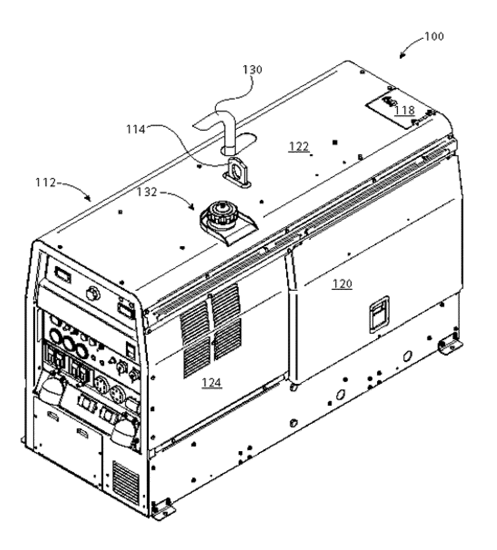
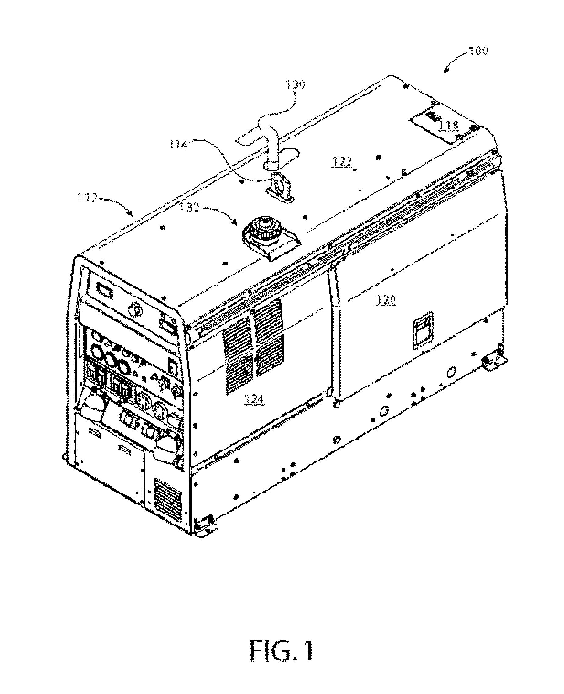
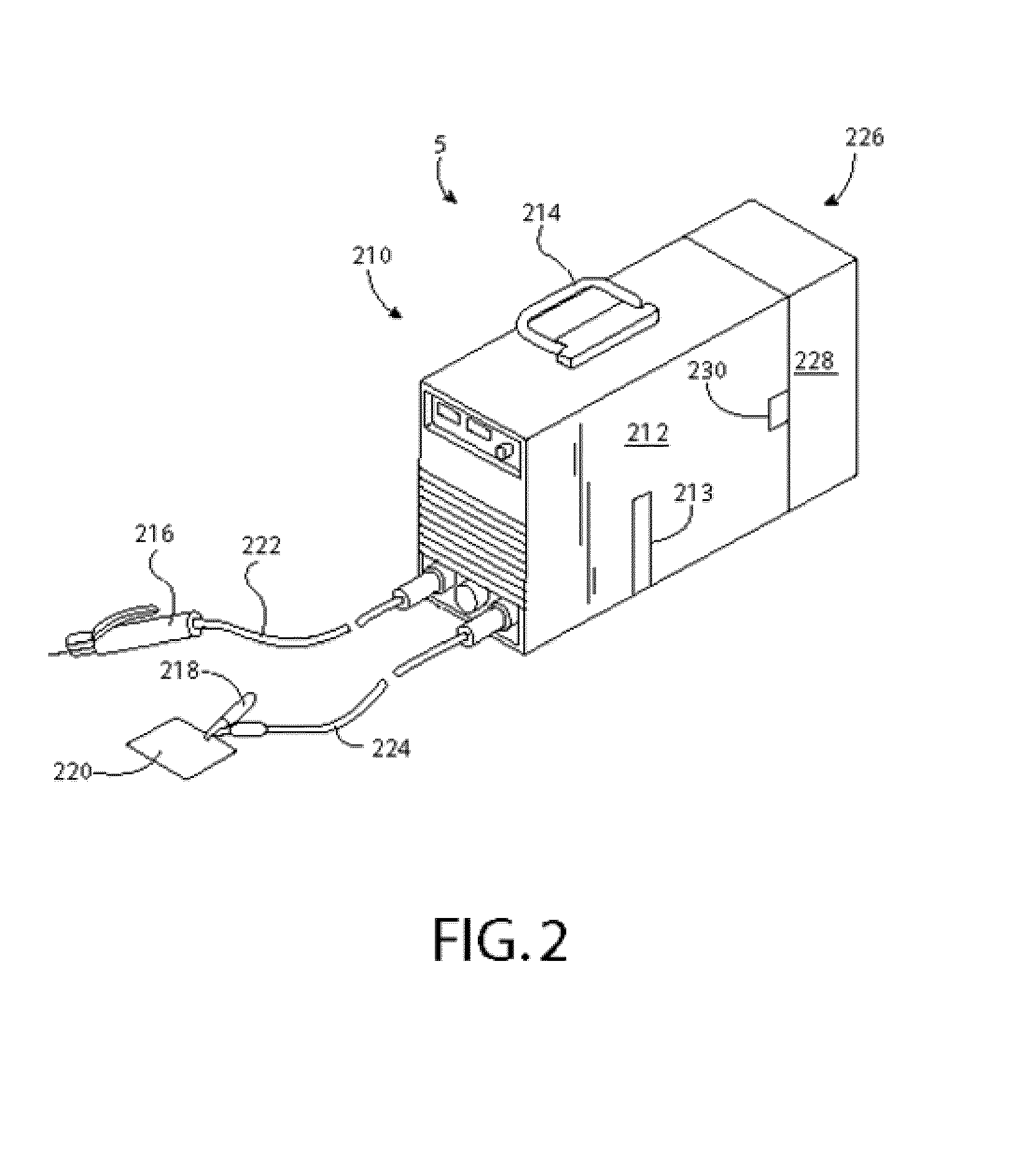
[0020]Embodiments of the invention relate to methods and systems that generally relate to utilizing a power source of an engine driven welder as a portion of a power supply for a hydraulic device associated with a vehicle. The hydraulic device can be incorporated into a vehicle, a stand-alone device, or a combination thereof. One or more controllers can manage power distribution and identify power sources for the hydraulic device based upon a parameter. In an embodiment, a hydraulic device can be powered by a portion of the engine driven welder based on a manual selection by a user or whether a motor is available (e.g., running). In other embodiments, additional conditions can be evaluated to identify one or more power sources for the hydraulic device.

[0021]The subject innovation can be used with any suitable engine-driven welder, engine-driven welding system, engine-driven welding apparatus, a welding system powered by an engine, a welding system powered by a battery, a welding sys...


PUM

PropertyMeasurementUnit
Temperatureaaaaaaaaaa
Poweraaaaaaaaaa
Efficiencyaaaaaaaaaa

Abstract

The invention described herein generally pertains to a system and method for utilizing a power source of an engine driven welder as a portion of a power supply for a hydraulic device associated with a vehicle. The hydraulic device can be incorporated into a vehicle, a stand-alone device, or a combination thereof. One or more controllers can manage power distribution and identify power sources for the hydraulic device based upon a parameter.

Description

CROSS-REFERENCE TO RELATED APPLICATIONS[0001]This application claims the benefit of priority to U.S. Provisional Application Ser. No. 61 / 876,799, filed Sep. 12, 2013, and entitled “BI-DIRECTIONAL ENERGY SHARING FOR ENGINE DRIVEN WELDER.” The entirety of the aforementioned application is incorporated herein by reference.TECHNICAL FIELD[0002]The invention described herein pertains generally to a system and method that manages power between a welding device, a vehicle, and a hydraulic device that is partially integrated with the vehicle.BACKGROUND OF THE INVENTION[0003]Frequently, welding is required where supply power may not be readily available. As such, the welding power supply may be an engine driven welding power supply incorporating a generator. The generator may supply power to the welder as well as to other power tools as may be needed on site. As different applications require different versions of welders and power tools, the trailer may be designed to carry one of many diff...

Claims


Application Information

Patent Timeline
IPC IPC(8): B23K9/10B23K9/32
CPCB23K9/1006B23K9/327B23K9/1081
Inventor BURKHART, BRYAN SCOTTSTOCKTON, DARREN
Owner LINCOLN GLOBAL INC
Learn More