Seat

a seat and seat technology, applied in the field of seats, can solve the problems of seatback not being lifted or lowered with respect to the seat cushion, seatback not being well positioned at the seat surface of the seatback,

Active Publication Date: 2015-05-21
TACHI S CO LTD
View PDF88 Cites 16 Cited by
  • Summary
  • Abstract
  • Description
  • Claims
  • Application Information

AI Technical Summary

Benefits of technology

[0017]To achieve the object specified above, in the seat according to this invention, the seatback is an integral component, not divided into upper and lower halves. The lower end of the seatback is isolated from the seat cushion, not coupled to the rear end of the seat cushion. The seat cushion and the seatback are configured to move up and down relative to each other. Measures are taken at the rear end of the seat cushion and the lower end of the seatback, to provide no gap between the rear end of the seat cushion and the lower end of the seatback when the seat cushion and the seatback move relative to each other.

Problems solved by technology

Inevitably, the seatback cannot be lifted or lowered with respect to the seat cushion.
If the occupant sits deep in the seat, the lower half of the seatback will move backward, not preventing the occupant from sitting deep.
In consequence, the occupant cannot feel well fit at the seat surface of the seatback.
As a result, the occupant cannot feel well fit at the seat surface of the seatback.
However, the seatback is not configured to lift or lower.
If the seatback is lifted or lowered, however, its lower half supporting the occupant's waist will change in position, failing to make the occupant to feel that the waist is well fit in the seat.
The configuration in which the seatback can be lifted and lowered cannot be employed.
In any conventional configuration described above, the seatback cannot be adjusted in position in accordance with the occupant's physique, inevitably failing to make the occupant feel well fit at the seat surface.

Method used


Image

  • Seat
  • Seat
  • Seat

Examples


Embodiment Construction

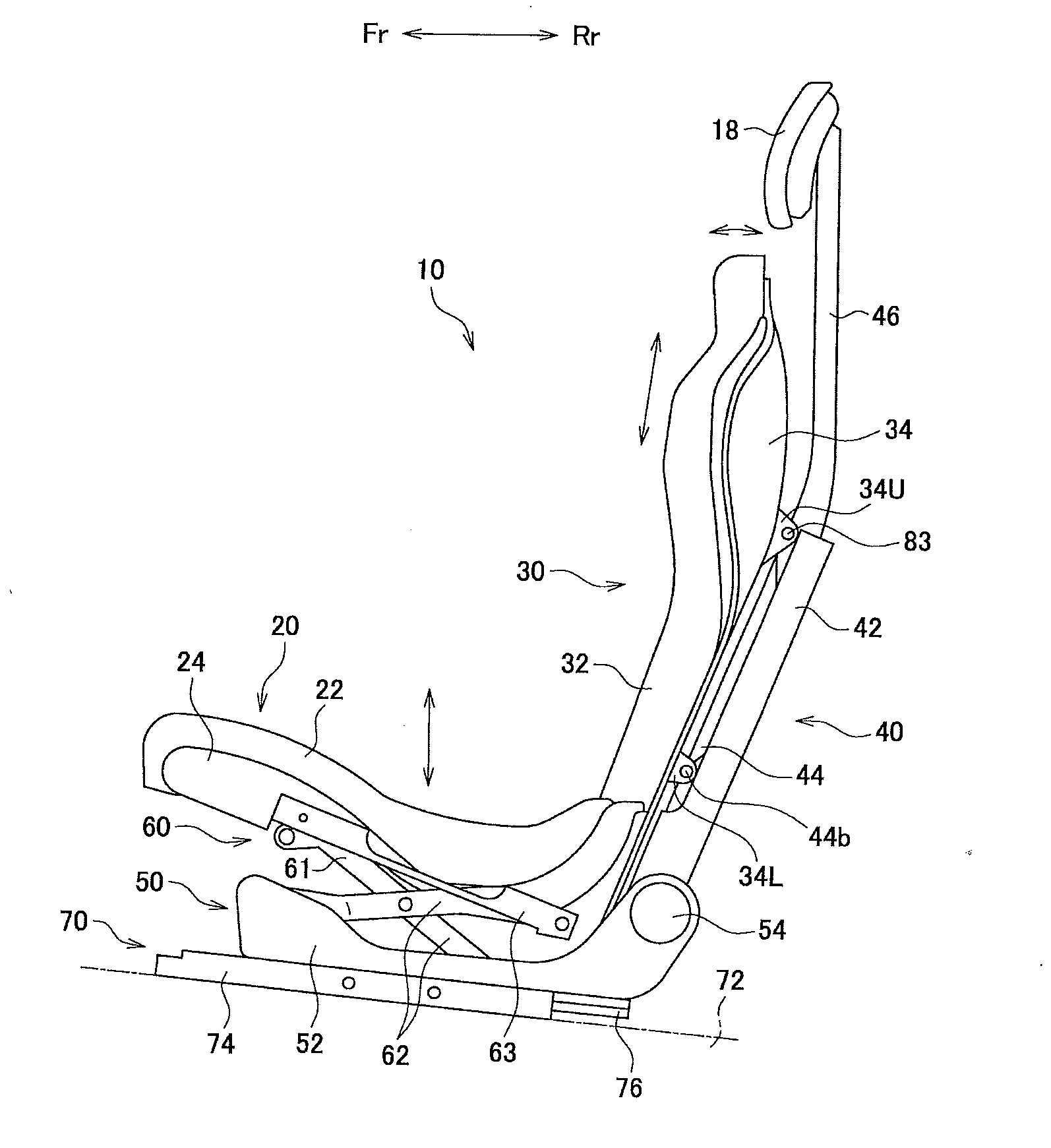
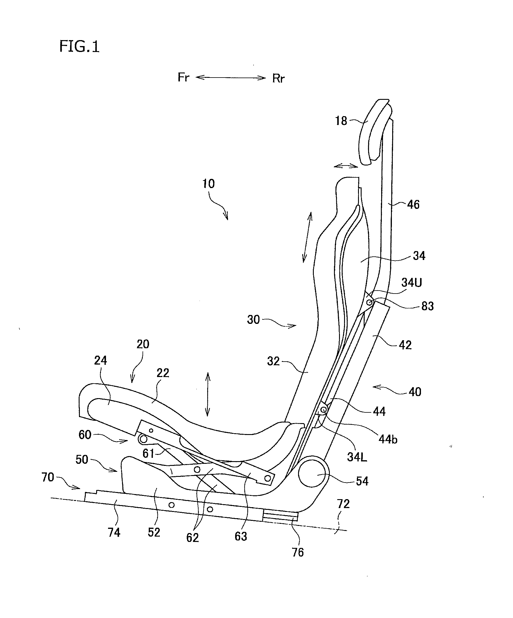
[0037]An embodiment of this invention will be described in detail, with reference to the accompanying drawings. The embodiment is a vehicle seat. In the drawing, Fr and Rr indicate the forward and backward directions with respect to the driver seated in the driver seat, and L and R indicate the leftward and rightward directions with respect to the driver.

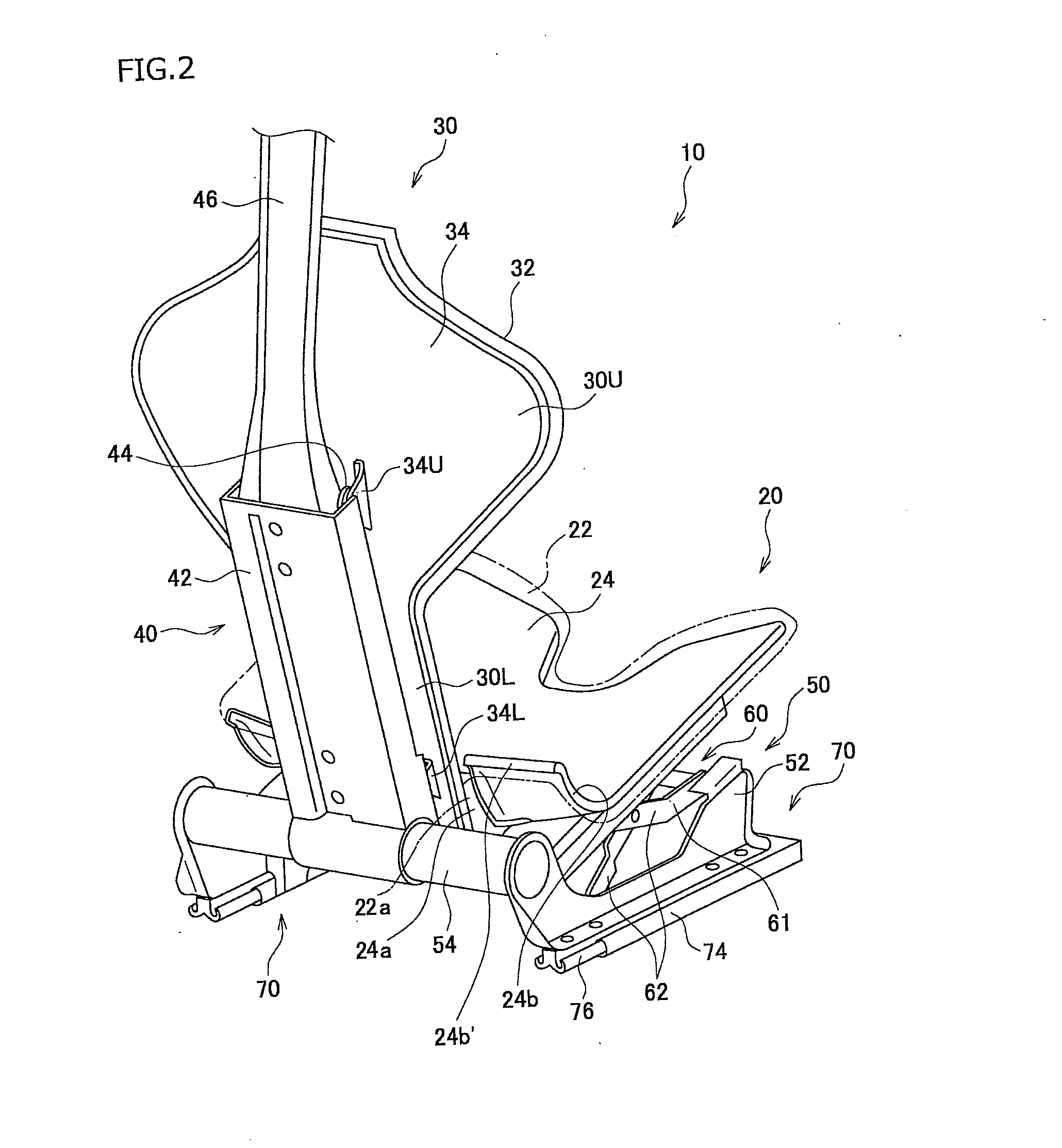
[0038]As shown in FIG. 1 and FIG. 2, the seat 10 is a vehicle seat, and comprises a seat cushion 20, a seatback 30, a strut 40, a riser 50 serving as base, a lifting / lowering means 60, and a seat sliding mechanism 70.

[0039]The seat cushion 20 comprises a seat cushion unit 22 composed of a pad and a trim cover covering the pad, and a cushion panel 24 holding the seat cushion unit 22. The seatback 30 comprises a seatback unit 32 composed of a pad and a trim cover covering the pad, and a back panel 34 holding the seatback unit 32. The cushion panel 24 and the back panel 34 are made of, for example, fiber-reinforced plastic (FRP). The s...


PUM


Abstract

A seat cushion is arranged on a riser. A strut is coupled, at lower end, to the rear end of the riser, and is provided at the back of the seat cushion. The seatback is secured to the strut, and is isolated from the seat cushion. The seatback and the seat cushion can therefore move, independent of each other. The seatback or the seat cushion, or both are lifted or lowered by a lifting/lowering means. Thus, the seatback and the seat cushion are lifted or lowered relative to each other. The lower half of the seatback, which supports the hips and lower ribs in the main, is made narrow than the upper half that supports the shoulder blades in the main. The seat cushion has, in the middle part of the rear end, a U-notch which loosely holds the narrow lower half.

Description

CROSS-REFERENCE TO RELATED APPLICATIONS[0001]This application is based upon and claims the benefit of priority from the prior Japanese Patent Application No. 2013-237580, filed Nov. 18, 2013, the entire contents of which are incorporated herein by reference.BACKGROUND OF THE INVENTION[0002]1. Field of the Invention[0003]This invention relates to a seat having a seatback that can be lifted and lowered and adjusted in position with respect to a seat cushion in accordance with the physique of the occupant.[0004]2. Description of the Related Art[0005]A vehicle seat is known, which has a seatback which front surface (seat surface) is shaped in conformity with the back of the occupant, to make the occupant feel that his or her back well fit in the seat. To make another occupant feel comfortable in the vehicle seat, the seatback must be lifted or lowered in accordance with this occupant's physique, particularly the height, thus adjusting the seat surface of the seatback in terms of positio...

Claims


Application Information

Patent Timeline
Patent Type & Authority Applications(United States)
IPC IPC(8): B60N2/16B60N2/22
CPCB60N2/1635B60N2/22B60N2/16B60N2/643B60N2/646B60N2/68B60N2/162B60N2/2231B60N2/2245B60N2002/2204B60N2/829B60N2/02258
Inventor KOIKE, ATSUSHIAMANO, TOMOHIROISHII, ATSUSHIKUMAGAI, KOTARO
Owner TACHI S CO LTD
Why Eureka
Try Eureka