Dynamic modeling method for torsional convex shoulder blade under elastic bearing based on variable section beam

A technology for blade dynamics and dynamic modeling, applied in special data processing applications, instruments, electrical digital data processing, etc., and can solve problems such as dynamic characteristic errors

Active Publication Date: 2018-11-13
NORTHEASTERN UNIV
View PDF1 Cites 14 Cited by
  • Summary
  • Abstract
  • Description
  • Claims
  • Application Information

AI Technical Summary

Problems solved by technology

However, the section change at the shoulder not only brings additional mass, but also additional stiffness, so only considering the impact of the additional mass brought by the shoulder cannot accurately reflect the real dynamic characteristics of the shoulder blade
In addition, fixed support is an ideal constraint condition, and it is impossible to achieve absolute fixed support in the installation of real blades, so the dynamic characteristics obtained by assuming the shoulder blade as a fixed constraint will have a large error
[0007] At present, the technology of dynamic modeling of rotating shoulder blades under elastic support conditions based on variable cross-section beams is in a blank state

Method used


Image

  • Dynamic modeling method for torsional convex shoulder blade under elastic bearing based on variable section beam
  • Dynamic modeling method for torsional convex shoulder blade under elastic bearing based on variable section beam
  • Dynamic modeling method for torsional convex shoulder blade under elastic bearing based on variable section beam

Examples


Embodiment 1

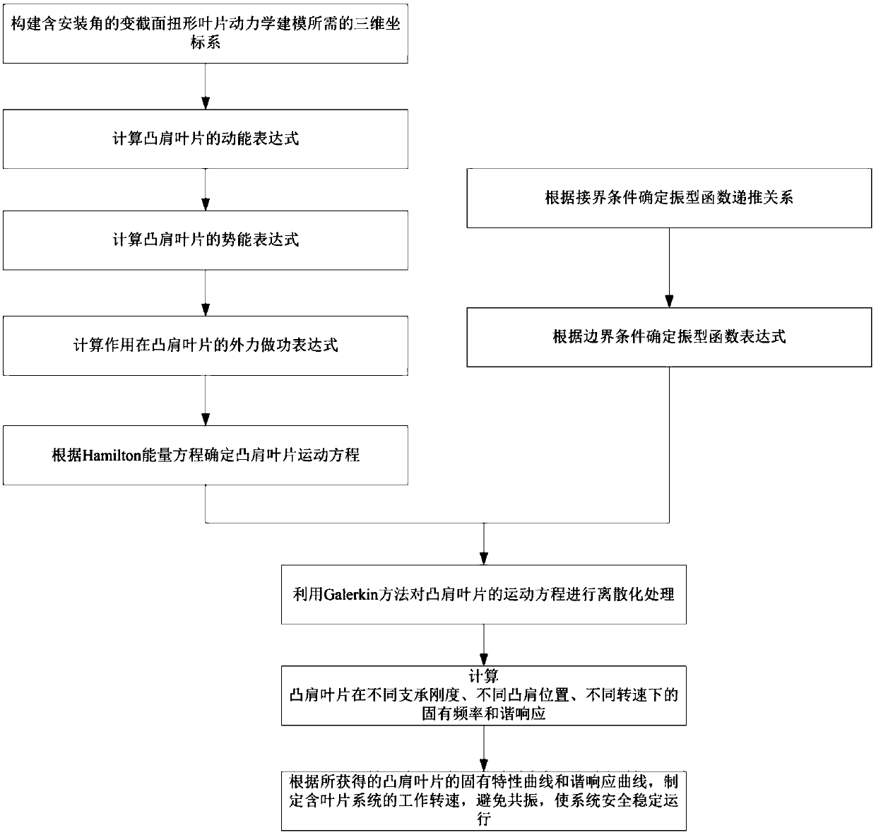
[0089] A dynamic modeling method for twisted shoulder blades under elastic support based on variable-section beams, such as figure 1 shown, including the following steps:

[0090] Step 1: Construct the three-dimensional coordinate system required for dynamic modeling of variable-section twisted blades with installation angles, including: the overall coordinate system OXYZ, and the coordinate system oxyz at the blade root.

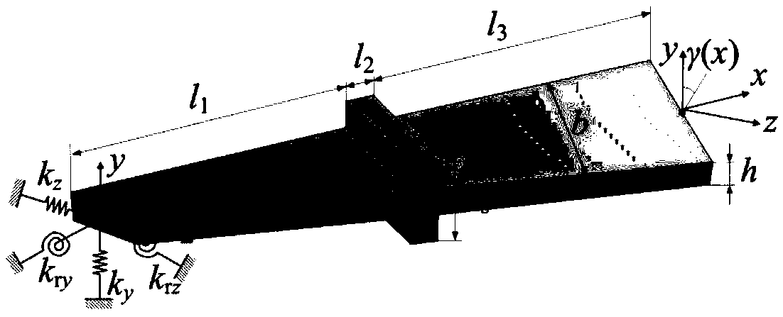
[0091] Step 2: Determine the structural parameters and material parameters of the blade, including blade length L, blade width b, blade thickness h, and wheel radius R d , Young's modulus E of blade, Poisson's ratio μ, blade density ρ. Shoulder thickness l 2 , the shoulder width h s ;

[0092] The stiffness k of the restraining spring and the restraining torsion spring of the blade in the bending direction y 、k ry , the stiffness k of the restraining spring and restraining torsion spring of the blade in the swing direction z 、k rz , the installation...

Embodiment 2

[0151] The schematic diagram of the variable cross-section rotating shoulder blade in the embodiment of the present invention is as follows figure 2 As shown, the dynamic modeling method of the twisted shoulder blade under the condition of elastic support includes the following steps:

[0152] Step 1: Obtain the structural parameters and material parameters of the blade system. The present invention assumes that the blade is an isotropic linear elastic material, and the constitutive relationship satisfies Hooke's law. The relevant parameters of the rotating blade are as shown in Table 1:

[0153] Table 1 Rotating Blade Parameters

[0154]

[0155]

[0156]Step 2: Considering the effect of the pre-twist angle of the plate, determine the displacement vector of any point on the shoulder blade in the global coordinate system OXYZ, and then calculate the kinetic energy expression of the blade:

[0157]

[0158]

[0159] Among them, u, v, w are the deformation of any p...


PUM


Abstract

The invention relates to a dynamic modeling method for a torsional convex shoulder blade under elastic bearing based on a variable section beam. The method is a dynamic modeling method for a section variable torsional convex shoulder blade having a mounting angle with the consideration to a rotation effect of the blade and an influence of the elastic bearing. According to the dynamic modeling method, the cost expense required by a blade dynamic experiment is saved; a geometrical structure of the blade is closer to a real blade, so by only modifying a structural dimension and material parameters of the blade, dynamic models of different blade systems can be obtained, and thus the operation is simple and convenient; dynamic characteristics of the dynamic modeling method can more reflect a real working state of the blade; a bearing manner of the dynamic modeling method is closer to a real assembly state of the blade; compared with that the dynamic characteristics of the blade are analyzedby virtue of traditional commercial finite element software, the dynamic modeling method provided by the invention has higher computational efficiency; and meanwhile, a rub-impact response analysis of a blade system can further be performed, thereby providing a design optimization for a system structure containing the blade.

Description

technical field [0001] The invention relates to a dynamic modeling method for twisted shoulder blades under elastic support based on variable-section beams, belonging to the technical field of mechanical dynamics Background technique [0002] At present, the existing dynamic modeling methods of shoulder blades mainly include the following methods: [0003] 1. Based on commercial finite element analysis software [0004] Import the CAD 3D model into the commercial finite element analysis software or directly build the 3D model in the finite element software, select the appropriate unit and material parameters, mesh the 3D model, establish the finite element model, set the appropriate constraints and select A suitable solution method is used to analyze the dynamic characteristics of the blade. However, when the existing commercial finite element analysis software is used to analyze the dynamic characteristics of twisted blades with installation angles, the modeling process i...

Claims


Application Information

Patent Timeline
Patent Type & Authority Applications(China)
IPC IPC(8): G06F17/50
CPCG06F30/13G06F30/20G06F2119/06
Inventor 马辉崔璨杨桐刘诗雨曾劲郭旭民
Owner NORTHEASTERN UNIV
Why Eureka
Try Eureka