

Nail-based compliant hip fixation system
a technology of compliant hips and fixing devices, applied in the field of nail-based compliant hip fixation systems, can solve the problems of femoral head damage, fixation devices not always providing a successful outcome,
- Summary
- Abstract
- Description
- Claims
- Application Information
AI Technical Summary
Benefits of technology
Problems solved by technology
Method used
Image

Examples
example 1
Hip Fixation System With a Flexibly Mounted Sleeve
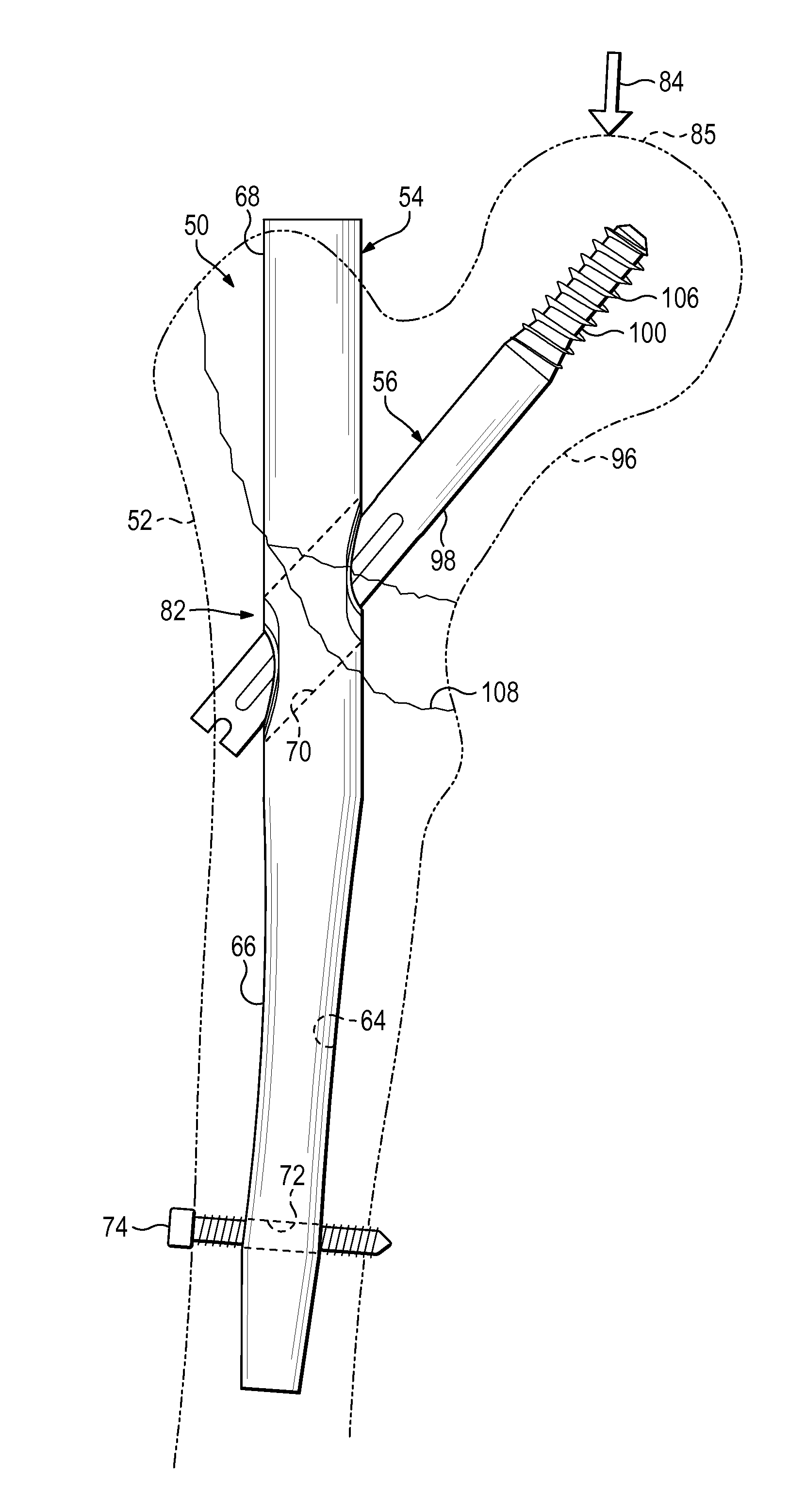
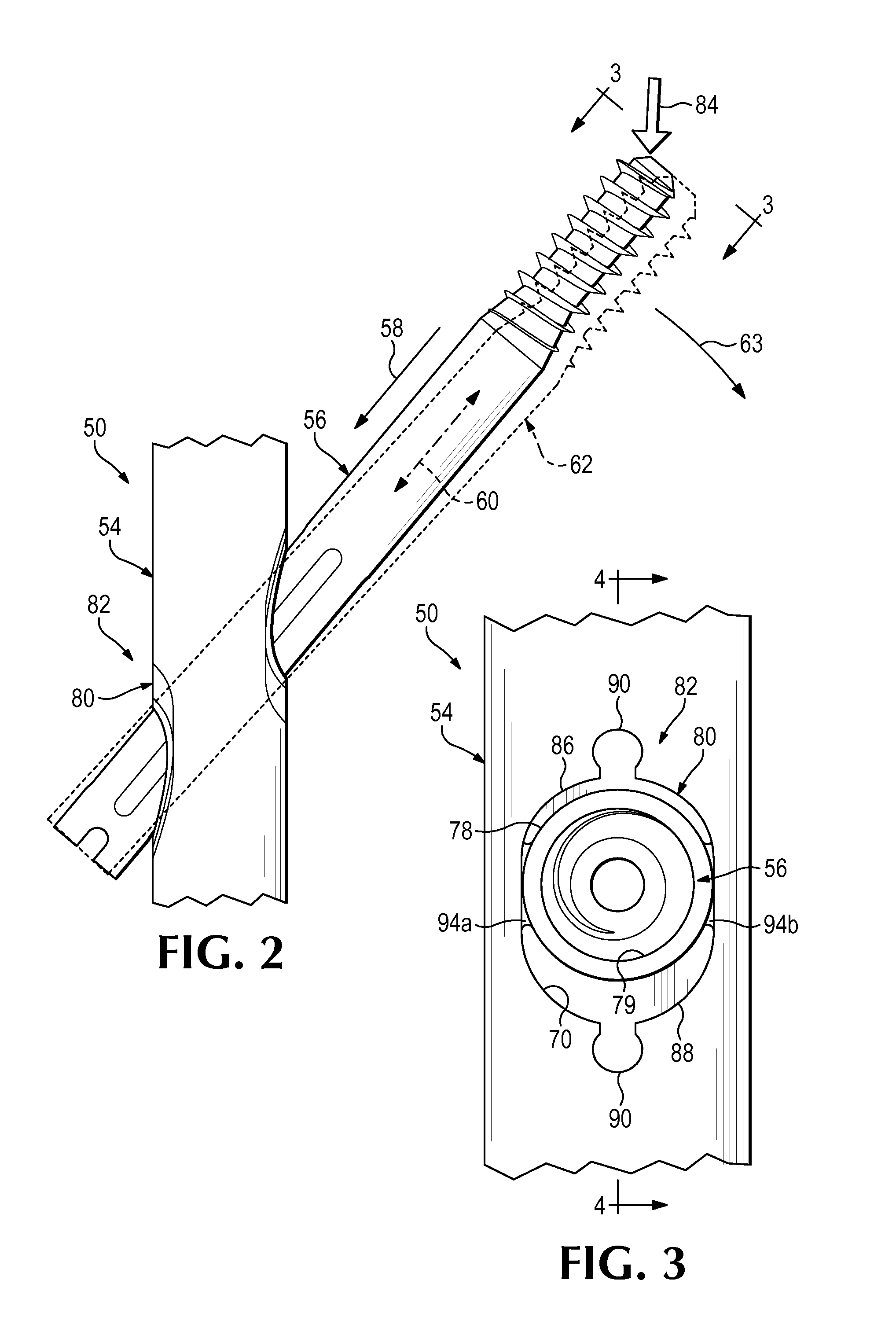
[0066]This example describes an exemplary hip fixation system 120 having a bearing member structured as a sleeve 78, mounted in a nail 54 via a compliant member 80, and surrounding a portion of a sliding fixation element 56; see FIGS. 5 and 6.
[0067]System 120 may have any suitable combination of the elements and features described above for fixation system 50 (see FIGS. 1-4). For example, sleeve 78 may be mounted in proximal aperture 70 of nail 54 via a pair of deformable elements 86, 88 disposed respectively above and below the sleeve. Complementary surface features 92 at the interface between sleeve 78 and deformable elements 86, 88 may restrict slippage of the sleeve with respect to the deformable elements. In contrast to system 50 (e.g., see FIG. 4), the complementary surface features may be absent from the interface between deformable elements 86, 88 and the wall of transverse aperture 70, which may allow the deformable elements...
example 2
Hip Fixation System With a Spring Contained by a Nail
[0069]This example describes an exemplary hip fixation system 140 including a nail 54 that contains a compliant interface 82 including a compliant member 80 formed as a spring 142; see FIGS. 7-9.
[0070]Hip fixation system 140 may have any suitable combination of the elements and features described above for hip fixation systems 50 and 120 (see FIGS. 1-6). However, hip fixation system 140 may utilize spring 142 instead of deformable elements 86, 88, and sleeve 78 may be omitted (compare FIGS. 8 and 9 with FIGS. 3 and 4). Accordingly, fixation element 56 may be positioned in slideable contact with an inner wall of aperture 70 (see FIGS. 8 and 9).
[0071]Spring 142 may be located below fixation element 56. The spring may have one or more tabs 144 that are received in recesses (e.g., slots) defined in the wall of aperture 70, to retain the spring within the aperture. The spring may be supported by the nail at spaced positions, to create ...
example 3
Hip Fixation System with Threaded Insert for a Nail
[0072]This example describes an exemplary hip fixation system including a nail 54 that receives a discrete insert providing a sleeve to receive a portion of a fixation element 56.
[0073]The insert may be disposed in proximal aperture 70 of nail 54 and attached to the nail, such as with threaded engagement between an external thread of the insert and an internal thread defined by aperture 70. Fixation element 56 may extend slideably in the aperture of the insert. The insert may include or hold a compliant member to create a compliant interface. The compliant member may be formed separately from or integrally with a body of the insert. Further aspects of a threaded insert that may be suitable are described in U.S. Provisional Patent Application Ser. No. 61 / 913,611, filed Dec. 9, 2013, which is incorporated herein by reference.
PUM
 Abstract
Description
Claims
Application Information