

Self-locking inject/eject latch
a self-locking, latch technology, applied in the direction of keyhole guards, mechanical devices, fastening means, etc., can solve the problems of complex latches, and achieve the effects of small footprint, large and/or variable leverage ratio, and graceful shutdown of circuit packs
- Summary
- Abstract
- Description
- Claims
- Application Information
AI Technical Summary
Benefits of technology
Problems solved by technology
Method used
Image

Examples
Embodiment Construction
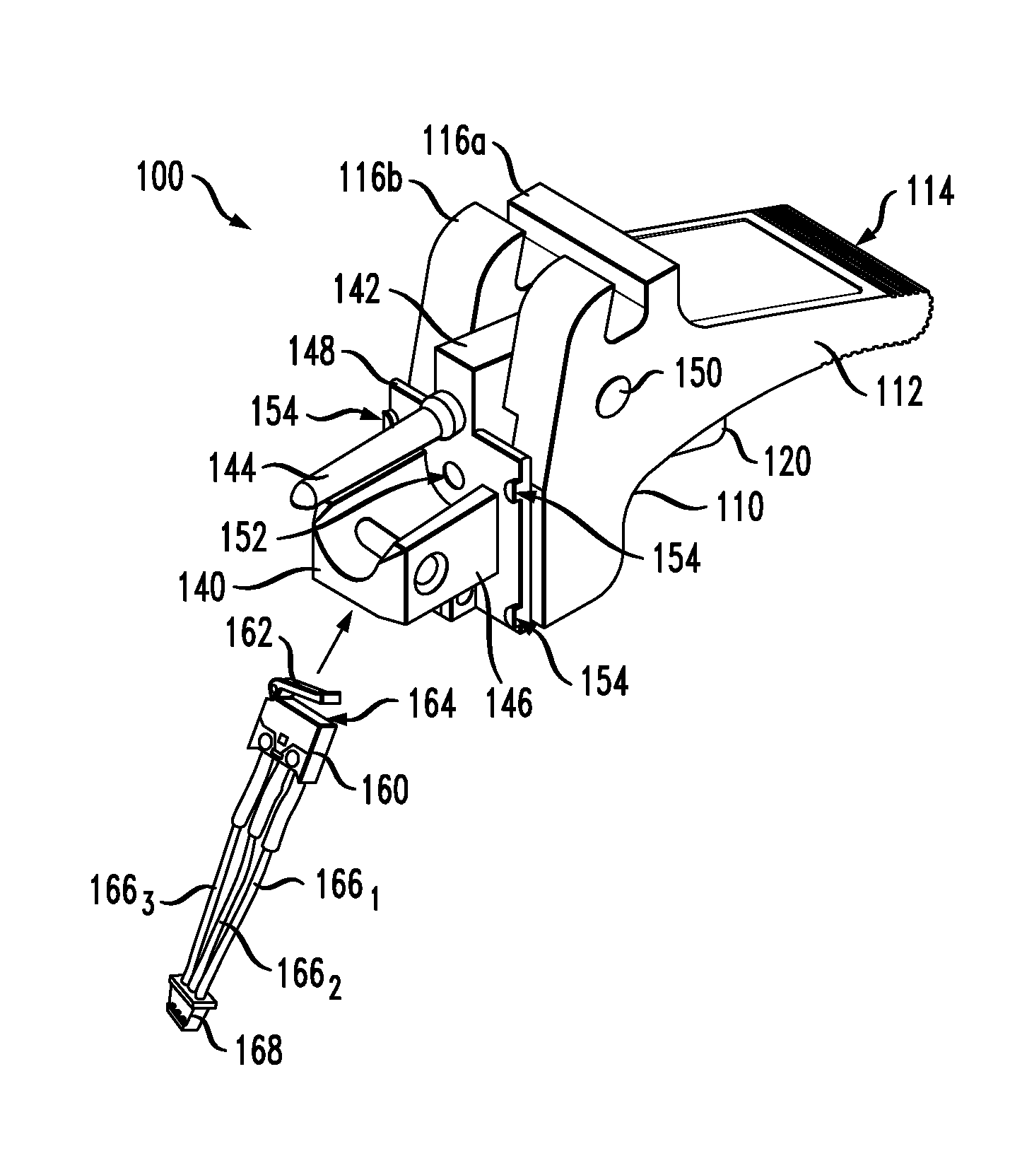
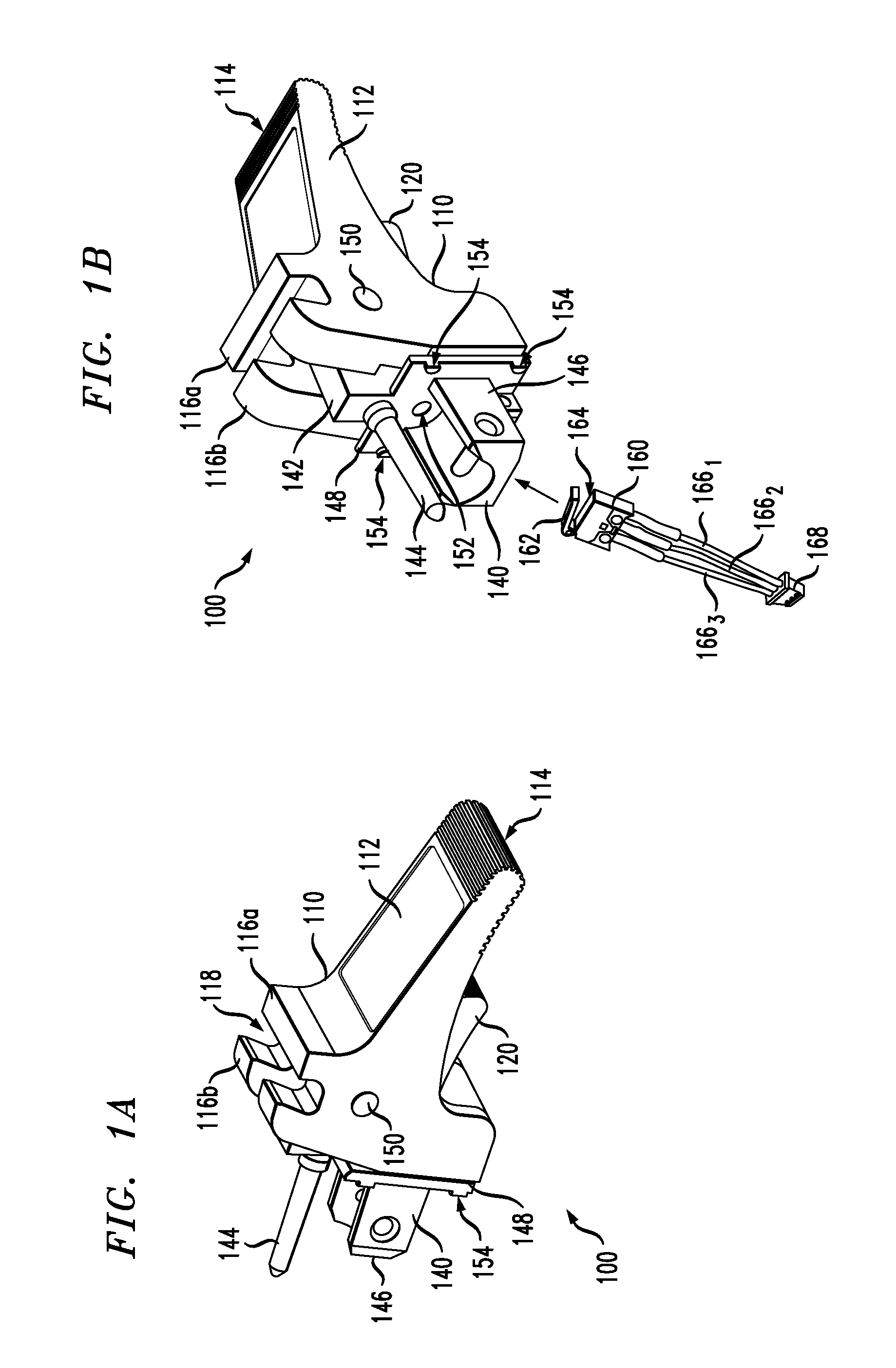
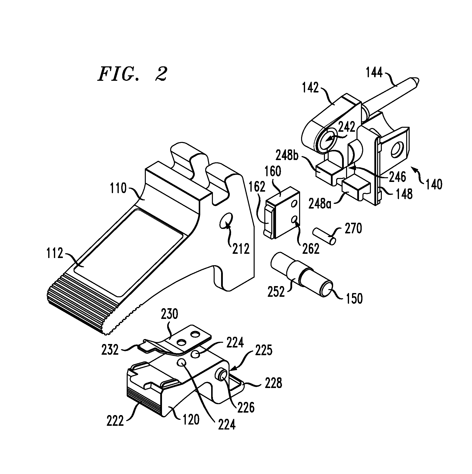
[0006]Disclosed herein are various embodiments of a self-locking inject / eject latch that can be used, e.g., as a mechanical aid for insertion / extraction of a corresponding circuit pack into / from a respective slot in a sub-rack or an equipment cabinet. The latch can also securely hold the circuit pack in the inserted position, e.g., to maintain the corresponding electrical and / or optical connections even when the circuit pack or the equipment cabinet is jarred or jostled. In an example embodiment, a handle of the latch contains a spring-biased locking lever configured to automatically lock the latch in the closed position when the pawl of the latching member engages the corresponding keeper. Some embodiments of the latch may include an integrated micro-switch that enables a graceful shutdown of the circuit pack, e.g., to avoid an extraction without a proper power-down. At least some embodiments of the latch may also have one or more of the following beneficial characteristics: (i) a ...
PUM
 Abstract
Description
Claims
Application Information