Plumbing bracket assembly

a technology of brackets and components, applied in the field of brackets and assemblies, can solve the problems of high cost, easy breakage of plastic brackets, and time-consuming sweat/soldering of certain copper-plated steel brackets on copper pipes

Active Publication Date: 2015-06-11
ERICO INT
View PDF11 Cites 29 Cited by
  • Summary
  • Abstract
  • Description
  • Claims
  • Application Information

AI Technical Summary

Benefits of technology

[0015]In an embodiment in combination with one or more other features of one or more other paragraphs of this section, the bracket body has multiple of the ...

Problems solved by technology

Among these are problems with a plastic bracket that comes in loose pieces and is time consuming to assemble, and that such a plastic bracket breaks easily when installing the supply line clamps over the pipes, and during ...

Method used


Image

  • Plumbing bracket assembly
  • Plumbing bracket assembly
  • Plumbing bracket assembly

Examples


Embodiment Construction

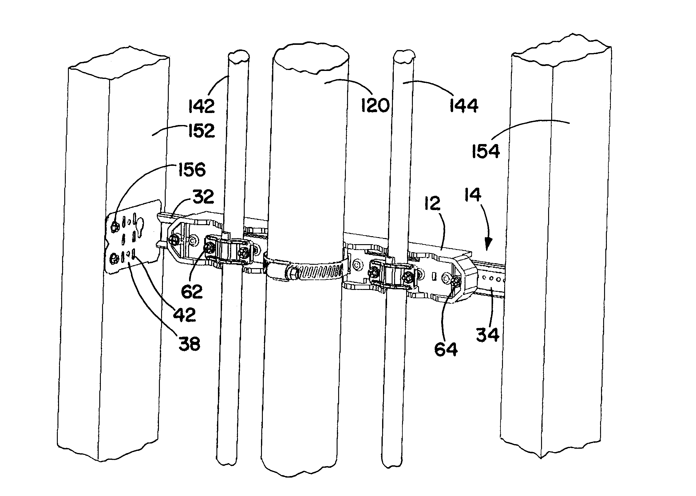
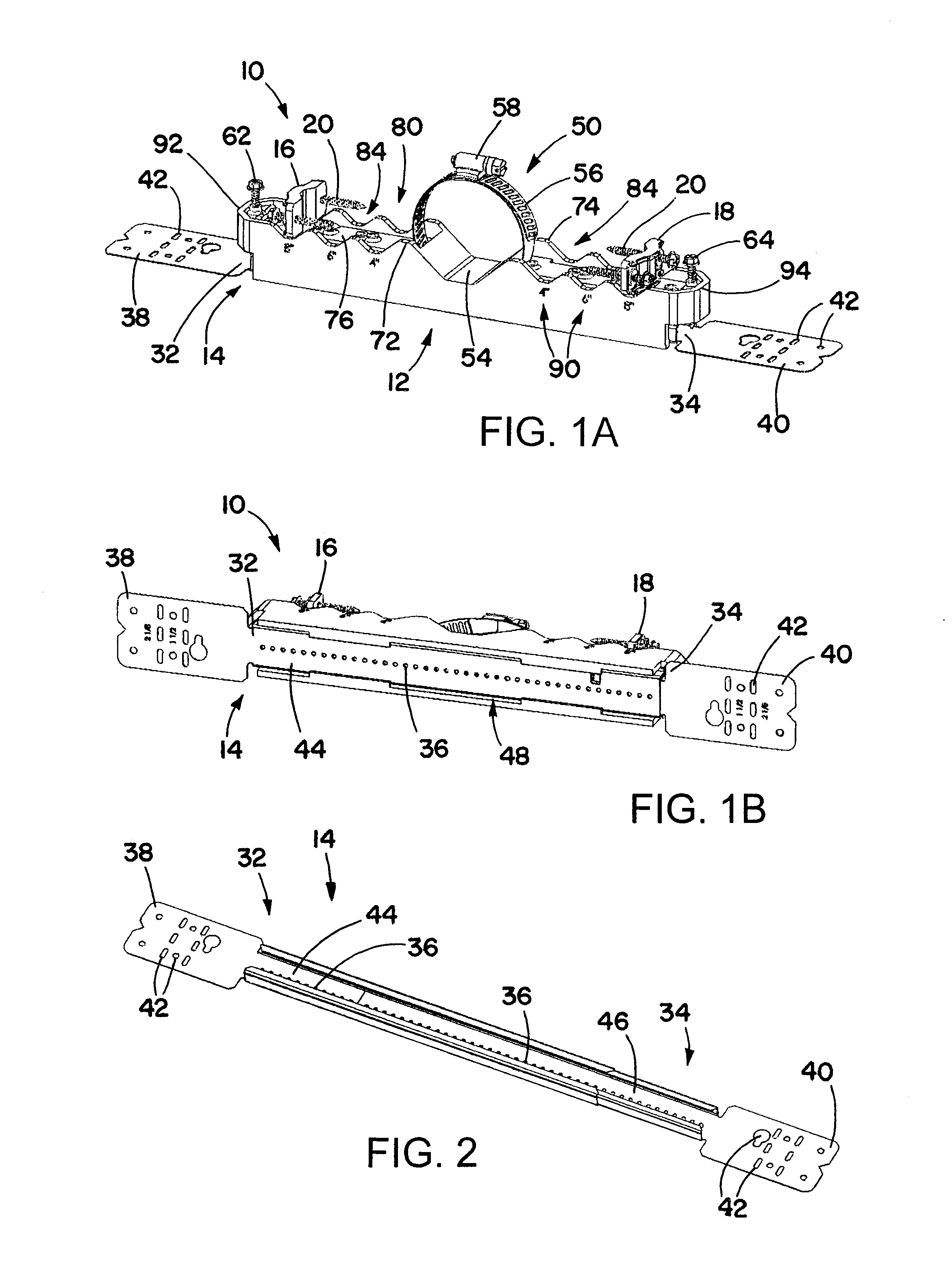
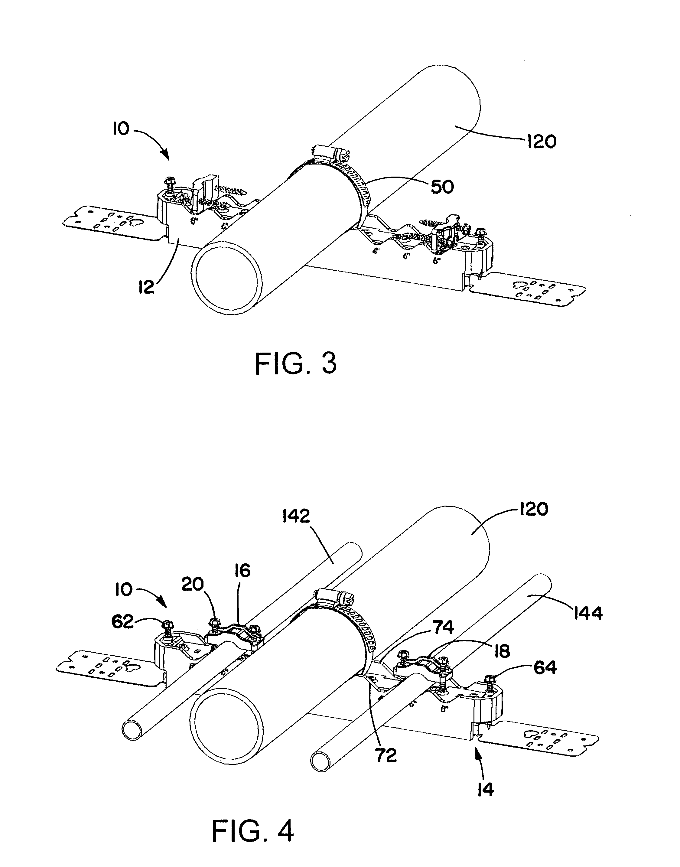
[0038]A plumbing bracket assembly has a plastic main bracket body and a telescoping bracket. The telescoping bracket runs through the main bracket body, and is able to extend to allow the bracket assembly to be secured to structure (such as studs) at both ends, over a range of distances between structure elements. The bracket body is initially able to slide along the telescoping bracket, for desired positioning, but may be locked in place using screws on the main bracket body. Hardware, such a hose clamp and multiple pipe clamps, is initially coupled to the main bracket body. The main bracket body may have a central depression for receiving a relatively large pipe run, and notches or depressions on opposite sides of the central depression, for receiving smaller pipe runs.

[0039]Referring initially to FIGS. 1A and 1B, a plumbing bracket assembly 10 is used to quickly fix pipe runs, for example supply pipes to a waste pipe, and then attach that assembly into a building's stud cavity. T...


PUM

PropertyMeasurementUnit
Diameteraaaaaaaaaa

Abstract

A plumbing bracket assembly has a plastic main bracket body and a telescoping bracket. The telescoping bracket runs through the main bracket body, and is able to extend to allow the bracket assembly to be secured to structure (such as studs) at both ends, over a range of distances between structure elements. The bracket body is initially able to slide along the telescoping bracket, for desired positioning, but may be locked in place using screws on the main bracket body. Hardware, such a hose clamp and multiple pipe clamps, is initially coupled to the main bracket body. The main bracket body may have a central depression for receiving a relatively large pipe run, and notches or depressions on opposite sides of the central depression, for receiving smaller pipe runs.

Description

[0001]This application claims priority under 35 USC 119 to U.S. Provisional Application 61 / 912,143, filed Dec. 5, 2013, the entirety of which is incorporated by reference herein.BACKGROUND OF THE INVENTION[0002]1. Technical Field of the Invention[0003]The invention is in the field of brackets and assemblies for plumbing installations.[0004]2. Description of the Related Art[0005]In making plumbing installations, waste pipes and supply pipes are often pre-fabbed or pre-assembled off-site, and then are installed together on a jobsite. Currently, contractors use inexpensive brackets to do this pre-fab work. Assemblies are fabricated in a shop, and then are shipped to a jobsite, where installers lift them into the stud wall and attach a mid-span support from the studs to the pipes. This method has been found to be the standard in many pre-fab shops throughout the country. There are many shortcomings in common products and methods for accomplishing. Among these are problems with a plastic...

Claims


Application Information

Patent Timeline
IPC IPC(8): F16L3/22F16L3/10
CPCF16L3/222F16L3/1058F16L3/1091F16L3/105
Inventor WILSON, JEFFREY A.OSBORN, ERIC C.AMBROGIO, NICHOLAS J.WILSON, ERIC J.
Owner ERICO INT
Why Eureka
Try Eureka