

Display device
a technology of display device and display case, which is applied in the direction of display/control unit casings, electric apparatus casings/cabinets/drawers, instruments, etc., can solve the problems of reducing light and eventually leaking outside, and achieve the effect of reducing or preventing bending and deformation of the separabl
- Summary
- Abstract
- Description
- Claims
- Application Information
AI Technical Summary
Benefits of technology
Problems solved by technology
Method used
Image

Examples
first preferred embodiment
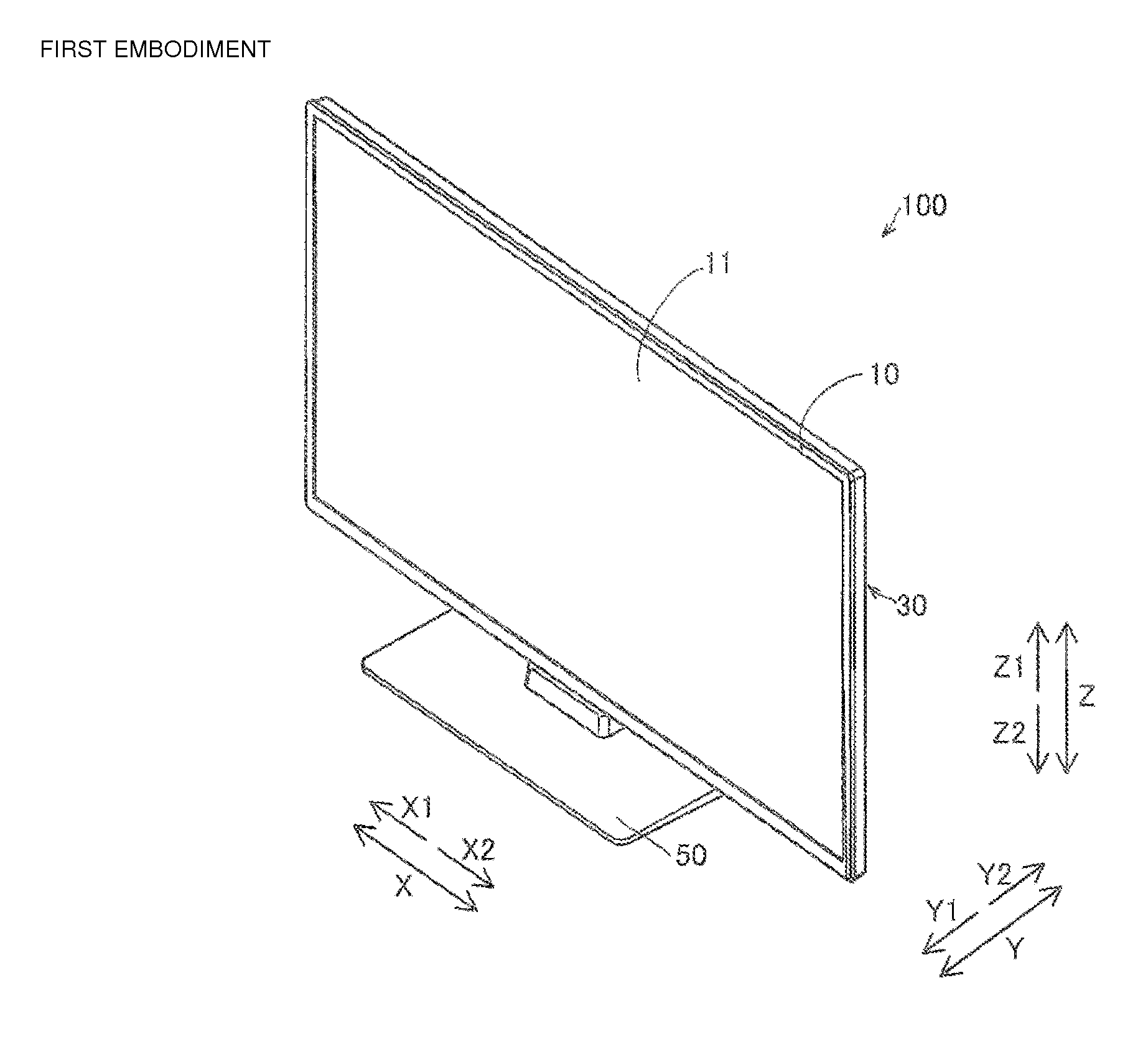
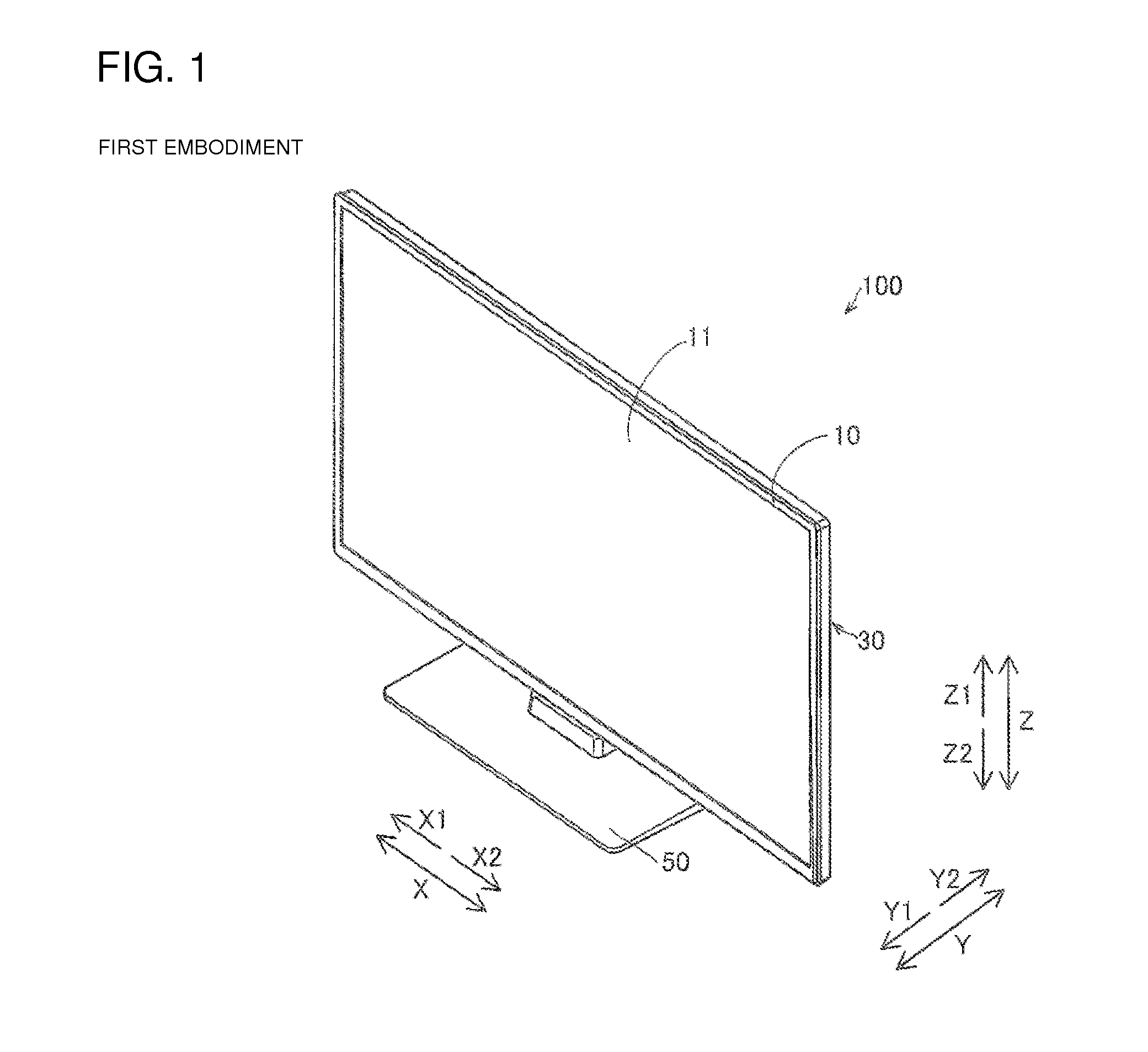
[0033]Referring to FIGS. 1 to 9, a structure of a television device 100 according to a first preferred embodiment of the present invention will be described. The television device 100 is an example of a “display device” according to the first preferred embodiment of the present invention.
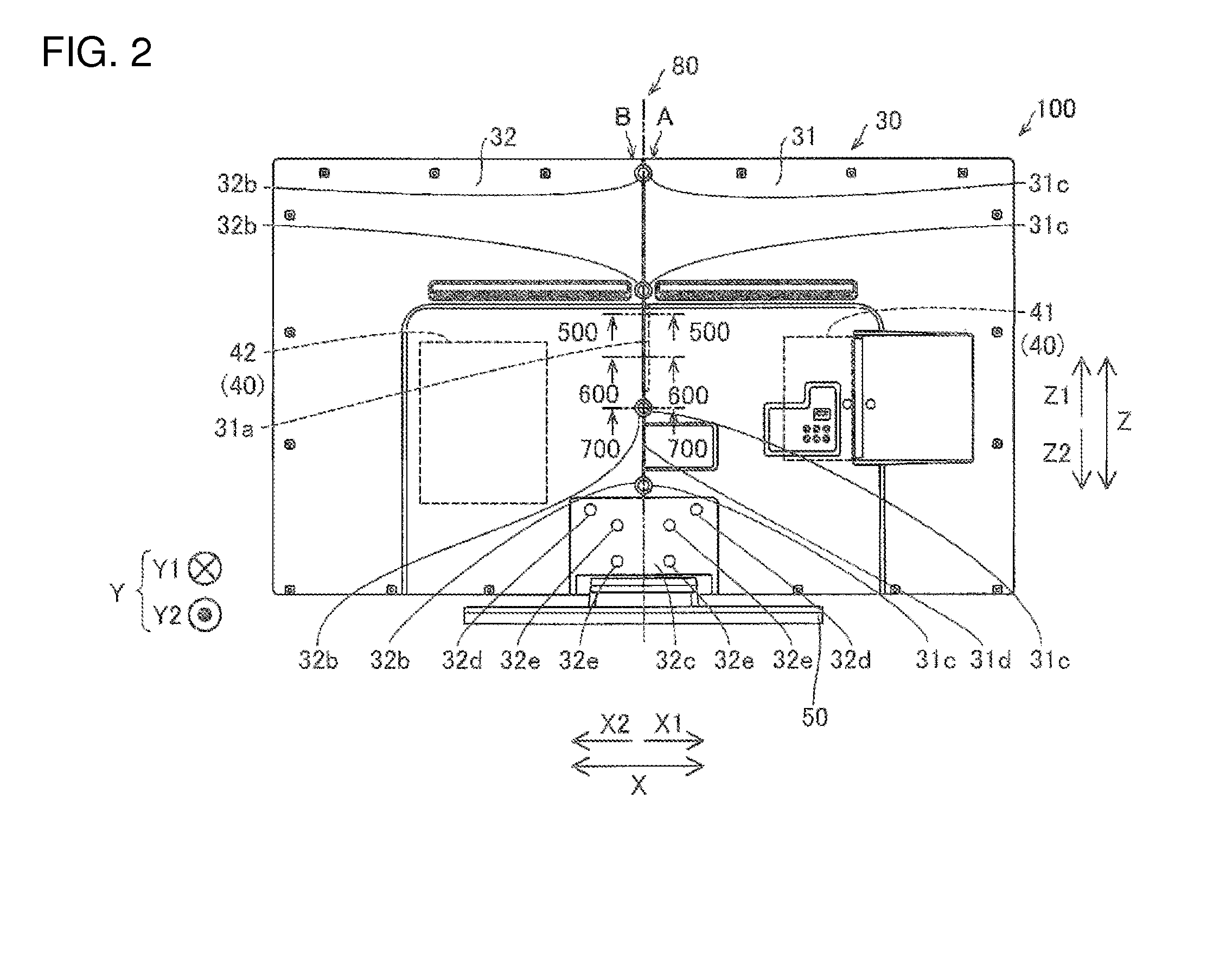
[0034]As illustrated in FIGS. 1 to 4, the television device 100 according to the first preferred embodiment of the present invention includes a display module 10 including a display panel 11 configured to display images and a rear frame 12 configured to support the display panel 11, a resin front housing 20 preferably has a rectangular or substantially rectangular frame shape in a front view (when viewed from the Y2 direction), and a resin rear housing 30 separable into a first separate member 31 and a second separate member 32.
[0035]The television device 100 further includes a circuit board 40 including a signal processing board 41 arranged in the inner side (the side in the Y1 direction) of the fi...
second preferred embodiment
[0066]A second preferred embodiment of the present invention will be described referring to FIGS. 6 to 10. Unlike the first preferred embodiment configured such that the signal processing board 41 and the power source board 42 are arranged in the inner sides (sides in the Y1 direction) of the first separate member 31 and the second separate member 32, respectively, the second preferred embodiment is configured such that a signal processing board 141 and a power source board 142 are both arranged in the inner side of the first separate member 31 as will be described below.
[0067]As illustrated in FIG. 10, the television device 200 according to the second preferred embodiment of the present invention includes a rear housing 130 which is configured to be separated into a first separate member 31 and a second separate member 132 preferably made of a resin material having lower fire-resistance than the first separate member 31 and a circuit board 140 including the signal processing board ...
third preferred embodiment
[0076]A third preferred embodiment of the present invention will be described referring to FIGS. 11 and 12. Unlike the first preferred embodiment which includes the rear housing 30 (130) separated into the first separate member 31 and the second separate member 32 (132), the third preferred embodiment is configured such that the rear housing 230 is separated into a first separate member 231, a second separate member 232, and a third separate member 233.
[0077]As illustrated in FIG. 11, a television device 300 according to the third preferred embodiment of the present invention includes the rear housing 230 separated into the first separate member 231, the second separate member 232, and the third separate member 233. The television device 300 further includes a circuit board 240 including a signal processing board 241 arranged in the inner side (the side in the Y1 direction) of the first separate member 231 and a power source board 242 arranged in the inner side of the second separat...
PUM
 Abstract
Description
Claims
Application Information