
See-through computer display systems

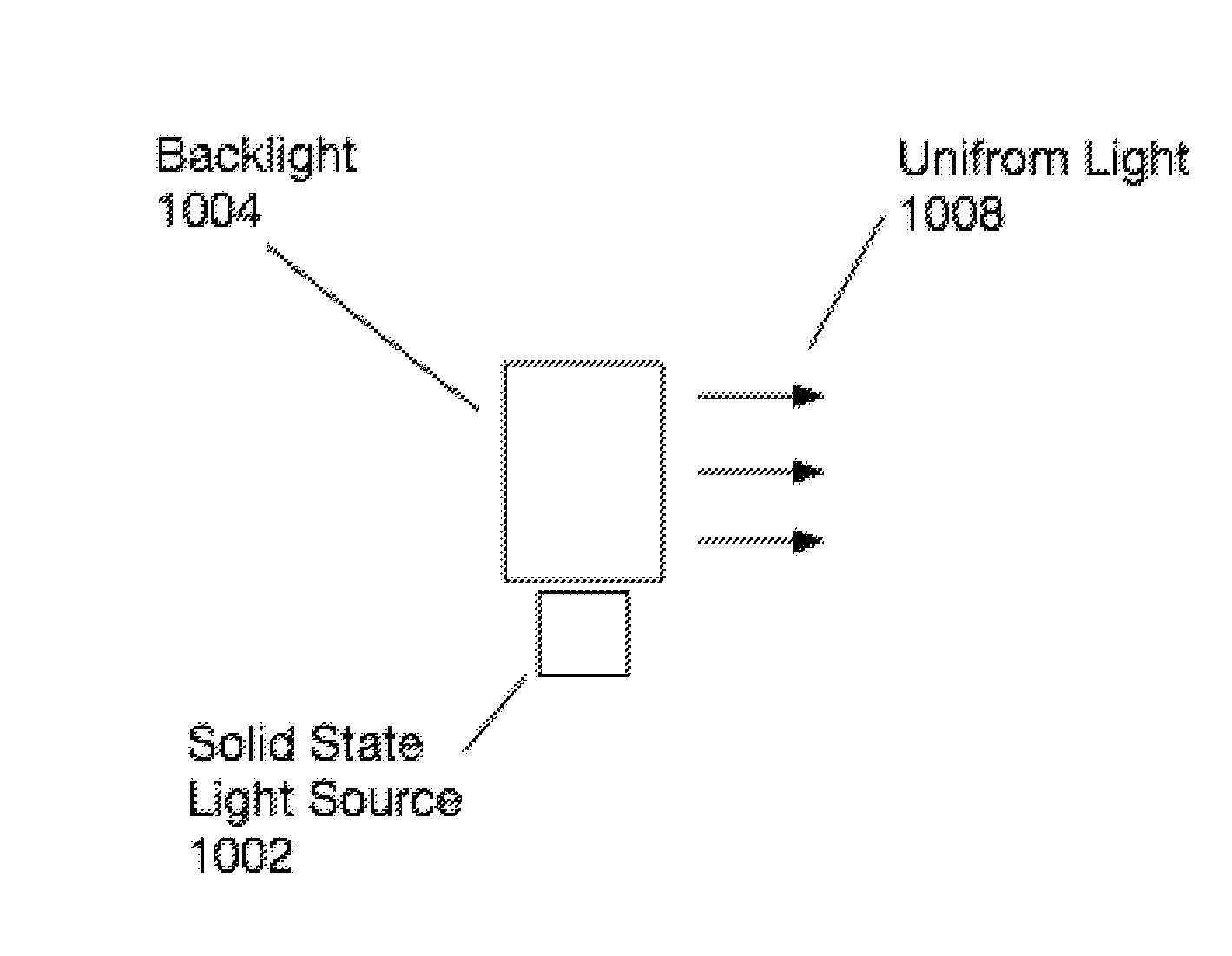
a display system and display screen technology, applied in the direction of instruments, lighting and heating equipment, planar/plate-like light guides, etc., can solve the problems of reducing the sharpness and contrast of the displayed image, and adversely affecting the see-through view of the environmen

Inactive Publication Date: 2015-07-23
OSTERHOUT GROUP INC
View PDF6 Cites 180 Cited by
  • Summary
  • Abstract
  • Description
  • Claims
  • Application Information

AI Technical Summary

Benefits of technology

The present invention is about methods and systems for see-through computer display systems. The technical effects of this invention include improved augmented reality and more realistic virtual conversations. These systems use special technology to display and show information that is overlapped with the real world, providing users with a more seamless and immersive experience. Overall, this patent aims to enhance the user's perspective and create a more see-through computer display system.

Problems solved by technology

This stray light reduces the sharpness and contrast of the displayed image in the HMD.
In addition, the stray light causes the black areas of the displayed image to be gray and this effect adversely affects the see-through view of the environment because the see-through view is produced by the combination of the light from the environment and the light from the displayed image, which is in the best case the black portions of displayed image.

Method used


Image

  • See-through computer display systems
  • See-through computer display systems
  • See-through computer display systems

Examples


Embodiment Construction

)

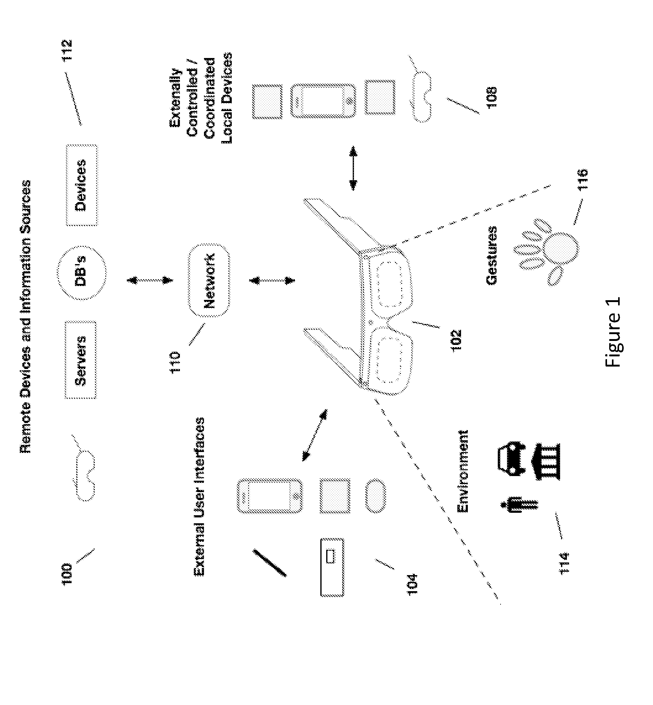
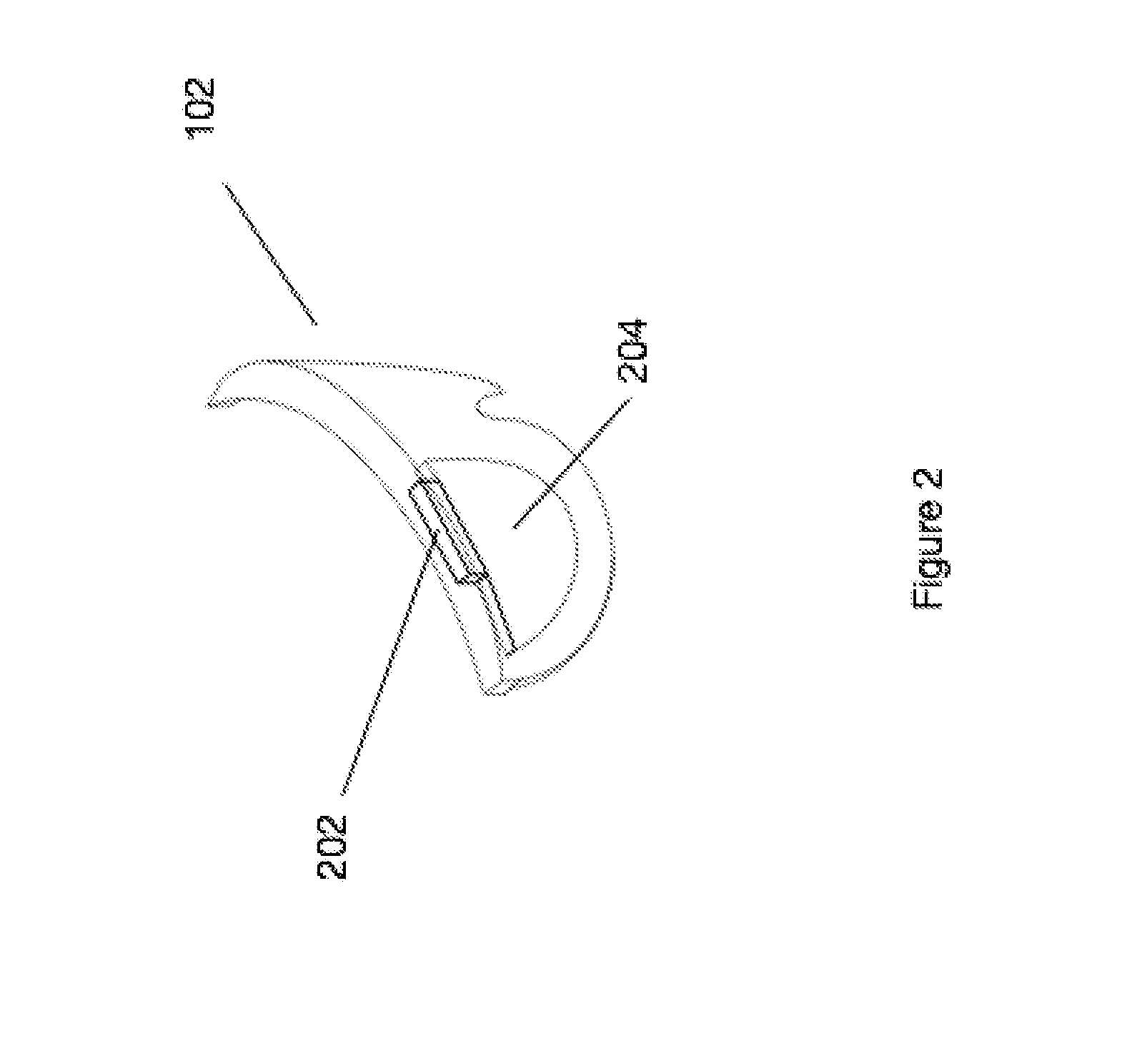
[0141]Aspects of the present invention relate to head-worn computing (“HWC”) systems. HWC involves, in some instances, a system that mimics the appearance of head-worn glasses or sunglasses. The glasses may be a fully developed computing platform, such as including computer displays presented in each of the lenses of the glasses to the eyes of the user. In embodiments, the lenses and displays may be configured to allow a person wearing the glasses to see the environment through the lenses while also seeing, simultaneously, digital imagery, which forms an overlaid image that is perceived by the person as a digitally augmented image of the environment, or augmented reality (“AR”).

[0142]HWC involves more than just placing a computing system on a person's head. The system may need to be designed as a lightweight, compact and fully functional computer display, such as wherein the computer display includes a high resolution digital display that provides a high level of emersion comprised...


PUM


Abstract

Aspects of the present invention relate to providing see-through computer display optics.

Description

CROSS REFERENCE TO RELATED APPLICATIONS[0001]This application claims the benefit of priority to and is a continuation of U.S. non-provisional application Ser. No. 14 / 561,146, entitled SEE-THROUGH COMPUTER DISPLAYS SYSTEM, filed Dec. 4, 2014.[0002]U.S. non-provisional application Ser. No. 14 / 561,146, entitled SEE-THROUGH COMPUTER DISPLAY SYSTEMS, filed Dec. 4, 2014 claims the benefit of priority to and is a continuation-in-part of the following U.S. patent applications, each of which is hereby incorporated by reference in its entirety:[0003]U.S. non-provisional application Ser. No. 14 / 160,377, entitled OPTICAL CONFIGURATIONS FOR HEAD WORN COMPUTING, filed Jan. 21, 2014.[0004]U.S. non-provisional application Ser. No. 14 / 172,901, entitled OPTICAL CONFIGURATIONS FOR HEAD WORN COMPUTING, filed Feb. 4, 2014 which is a continuation-in-part of U.S. non-provisional application Ser. No. 14 / 160,377, entitled OPTICAL CONFIGURATIONS FOR HEAD WORN COMPUTING, filed Jan. 21, 2014; and U.S. non-prov...

Claims


Application Information

Patent Timeline
IPC IPC(8): F21V8/00G02B27/01
CPCG02B6/0055G02B6/0073G02B27/0172G02B6/003G02B6/0031G02B6/0051G02B26/0833G02B2027/0194G02B2027/0118G02B27/1033G02B27/283G02B2027/0187G02B2027/0138G02B2027/0178H04N23/51H04N23/54G02B27/0101G02B27/0176G02B27/144G02B27/0093G02B27/10G02B2027/015G02B2027/0152G02B2027/0174
Inventor BORDER, JOHN N.HADDICK, JOHN D.
Owner OSTERHOUT GROUP INC
Features
  • Generate Ideas
  • Intellectual Property
  • Life Sciences
  • Materials
  • Tech Scout
  • Unparalleled Data Quality
  • Higher Quality Content
  • 60% Fewer Hallucinations
Learn More