Spring Operated Doorstop with Foot Release

a technology of springs and doorstops, applied in the direction of construction fastening devices, construction means, construction, etc., can solve the problem of being weak enough to be easily pulled from the wall or the hub

Inactive Publication Date: 2015-07-30
LOTT GEORGE F
View PDF14 Cites 10 Cited by
  • Summary
  • Abstract
  • Description
  • Claims
  • Application Information

AI Technical Summary

Problems solved by technology

The magnet is strong enough to hold the weight of the door

Method used


Image

  • Spring Operated Doorstop with Foot Release
  • Spring Operated Doorstop with Foot Release
  • Spring Operated Doorstop with Foot Release

Examples


Embodiment Construction

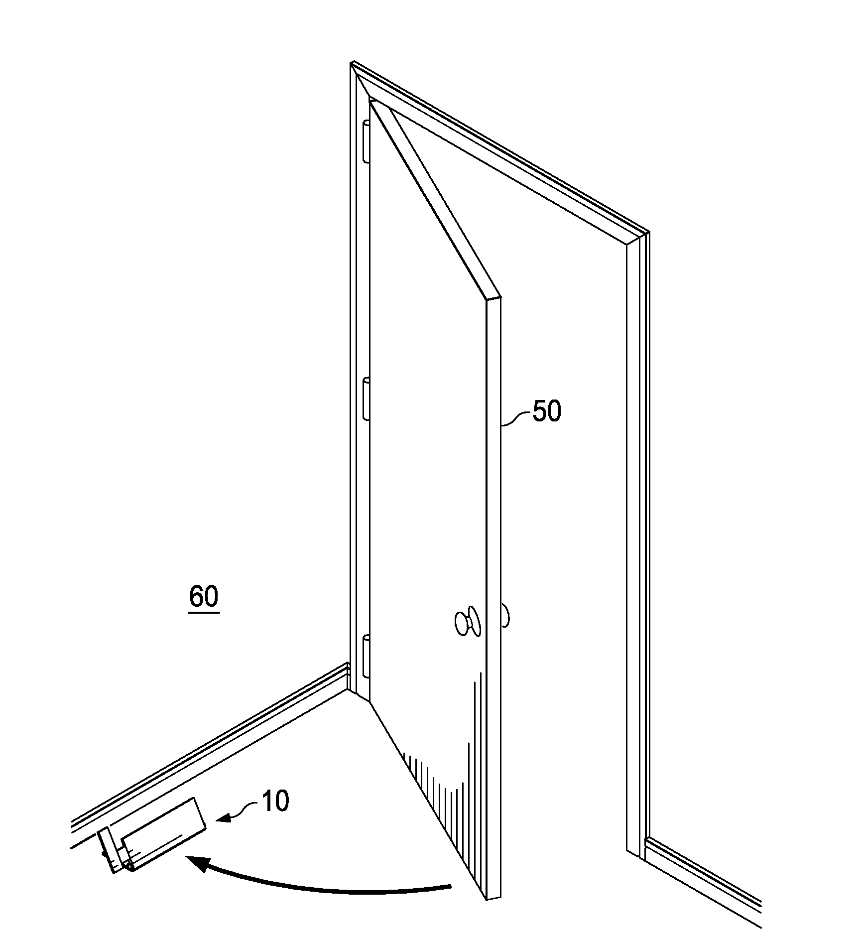
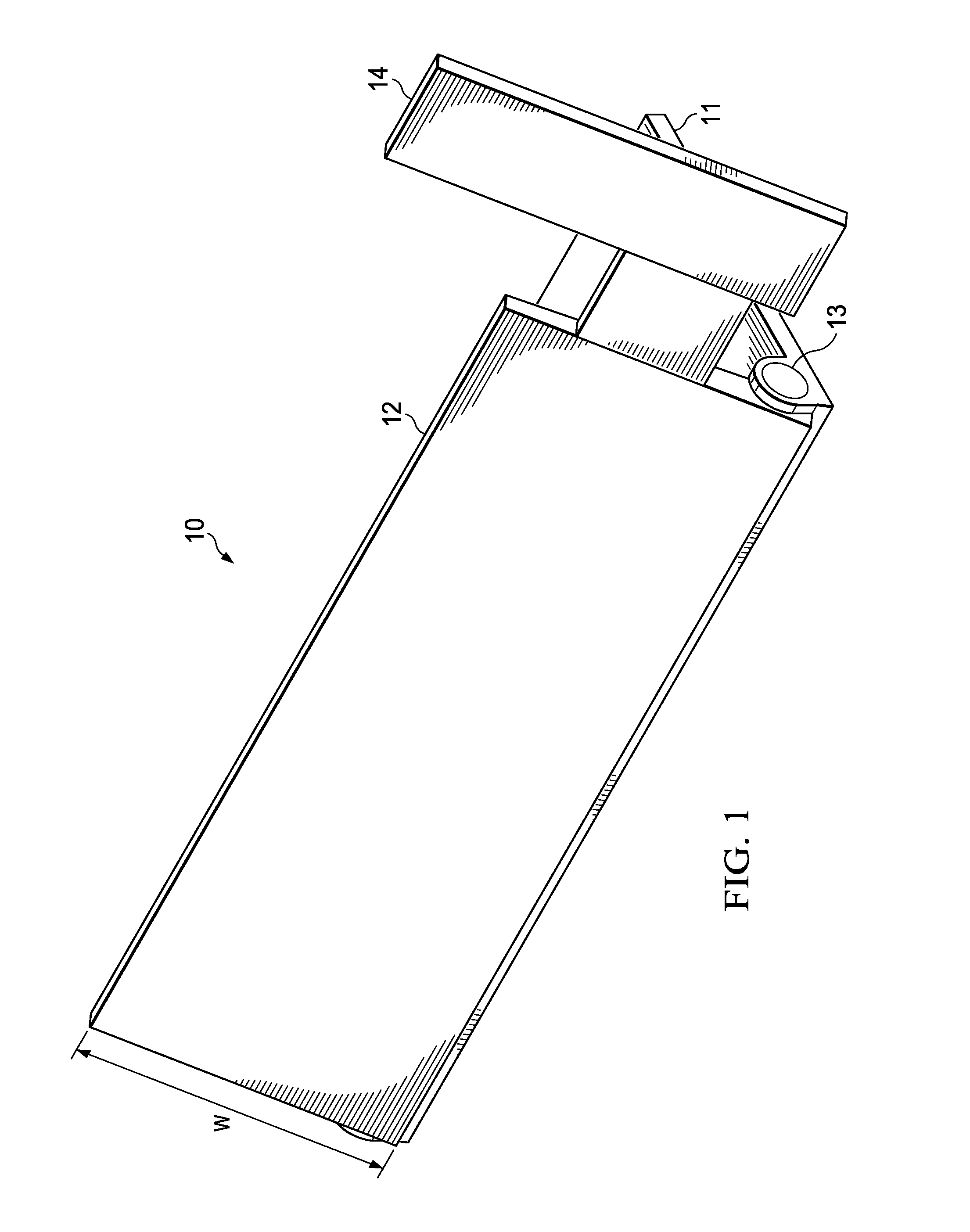
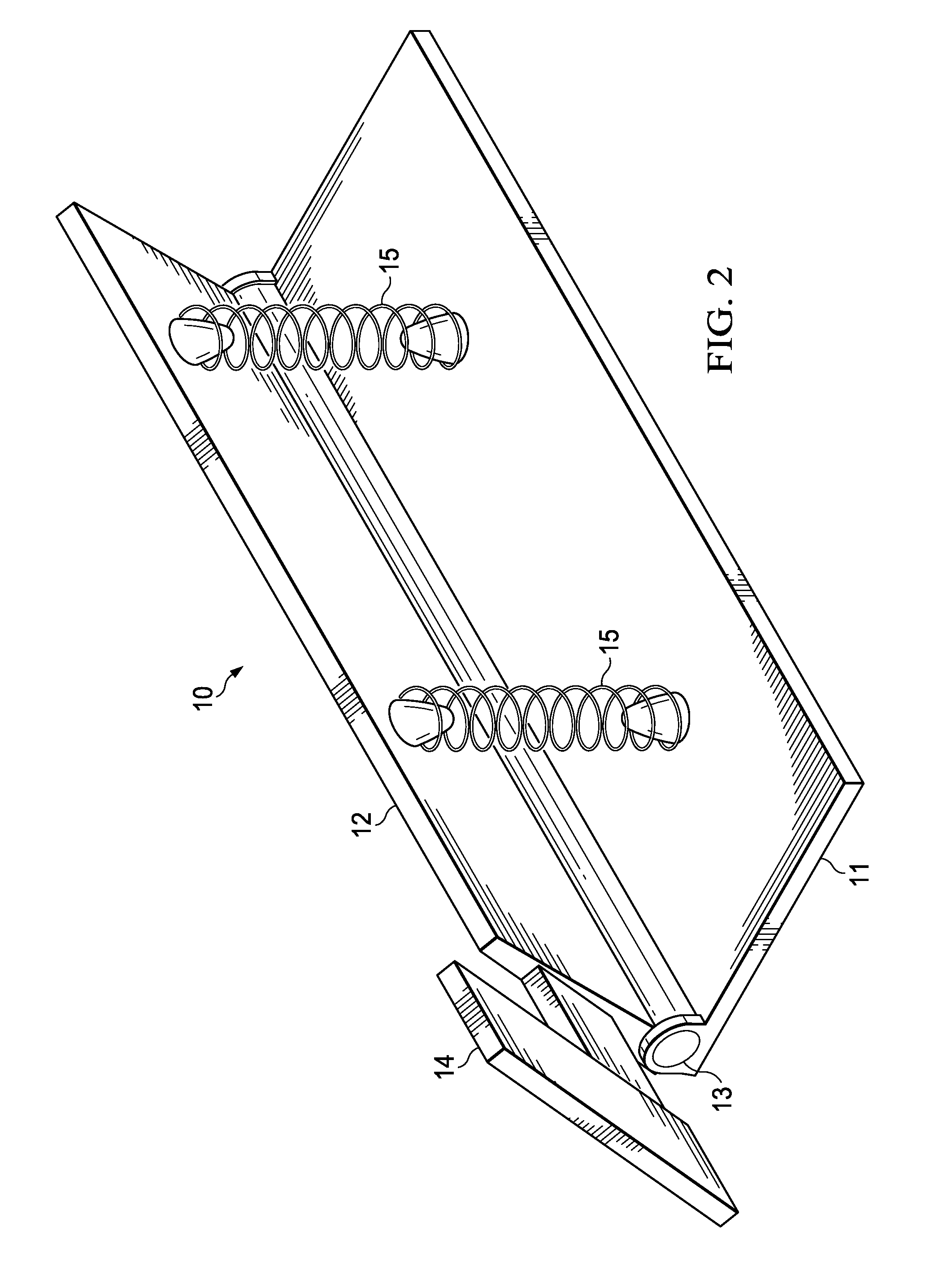
[0014]FIGS. 1 and 2 are both perspective views of the doorstop 10, as viewed from its hinged and non-hinged sides, respectively. FIG. 1 illustrates the doorstop 10 viewed from its hinged side, whereas FIG. 2 illustrates the doorstop 10 from its non-hinged (open) side. In both FIGS. 1 and 2, the doorstop 10 is in its “normally open” position.

[0015]Doorstop 10 comprises a base plate 11, top plate 12, hinge 13, foot pedal 14, and spring 15. Hinge 13 attaches a straight edge of base plate 11 to a straight edge of top plate 12.

[0016]Spring 15 holds top plate 12 apart from base plate 11, when doorstop 10 is in its open position. In other words, spring 15 provides a spring force that pushes top plate 12 apart from bottom plate 11. The size and spring force of spring 15 may vary, but generally spring 15 is configured to hold doorstop 10 in the “normally open” position of FIGS. 1-3.

[0017]In the example of FIGS. 1 and 2, spring 15 is a compression spring, but various types of springs may be s...


PUM


Abstract

A spring-operated doorstop for holding a door in an open position. The doorstop has a flat thin base plate for permanent attachment on a floor, and a top plate hinged to the base plate. A spring holds the top plate apart from the base plate, such that when the spring is in a non-compressed state, the angle between the base plate and the top plate is a set angle. A foot pedal is rigidly attached to the top plate. The doorstop is installed near the wall with the hinge facing outward, so that when the door is opened toward the wall and over the door stop, the spring momentarily compresses. It then springs back, so that the top plate will prevent the door from unwanted re-closing. The foot pedal may be used to hold the top plate down when the door is desired to be closed.

Description

TECHNICAL FIELD OF THE INVENTION[0001]This invention relates to stops for holding doors open, and more particularly to floor-mounted door stops.BACKGROUND OF THE INVENTION[0002]In the most general sense, a “doorstop” can be any one of various objects or devices used to hold a door open or closed, or to prevent a door from opening too widely.[0003]To hold a door open, the door stop may simply be a heavy solid object placed in the path of the door. These objects can range from spontaneously improvised objects, chosen simply because they are heavy, to artistic or whimsical designs.[0004]Another type of doorstop is the ubiquitous wedge-type door stop, which is a small wedge of wood, rubber, plastic, or other material. Manufactured wedges of these materials are commonly available. The wedge is kicked into position and the downward force of the door, now jammed upwards onto the doorstop, provides enough static friction to keep it motionless.[0005]A third strategy is to equip the door with...

Claims


Application Information

Patent Timeline
IPC IPC(8): E05C17/02
CPCE05C17/02E05C17/50Y10T292/71
Inventor LOTT, GEORGE F.
Owner LOTT GEORGE F
Why Eureka
Try Eureka