Illuminator and projector

Active Publication Date: 2015-08-20
SEIKO EPSON CORP
View PDF2 Cites 0 Cited by
  • Summary
  • Abstract
  • Description
  • Claims
  • Application Information

AI Technical Summary

Benefits of technology

[0019]Since the configuration of the projector related to the second aspect includes any of the illuminators described above, the performance of the projector itself, for example

Problems solved by technology

In the illuminator described above, however, any variation in the position of the mounted laser light source or collimator lens undesirably shifts the direction of the principal ray of light in

Method used


Image

  • Illuminator and projector
  • Illuminator and projector
  • Illuminator and projector

Examples


Embodiment Construction

[0026]An embodiment of the invention will be described below in detail with reference to the drawings.

[0027]In the drawings used in the following description, a characteristic portion is enlarged for convenience in some cases for clarify of the characteristic thereof, and the dimension ratio and other factors of each component are therefore not always equal to actual values.

Projector

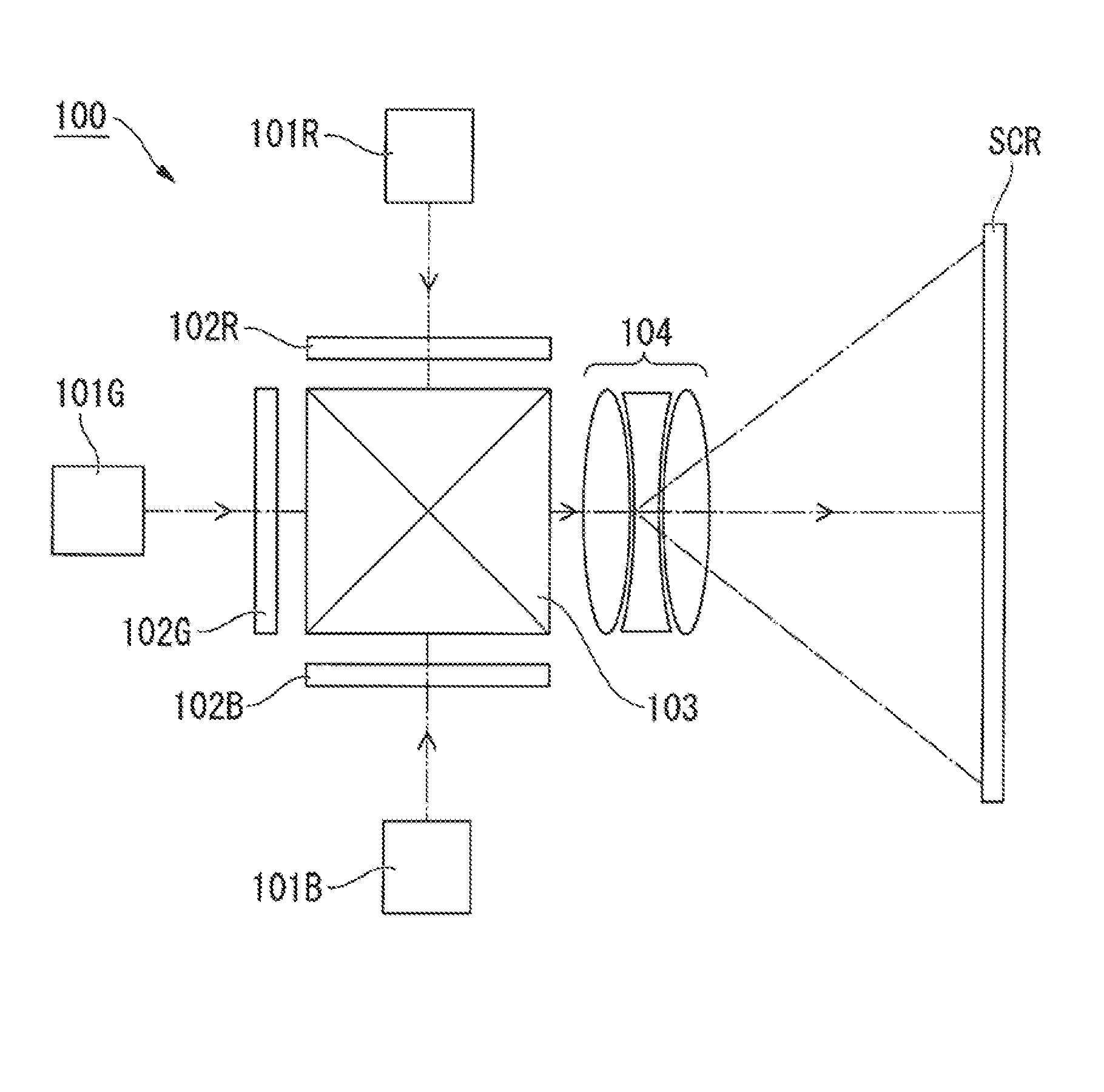
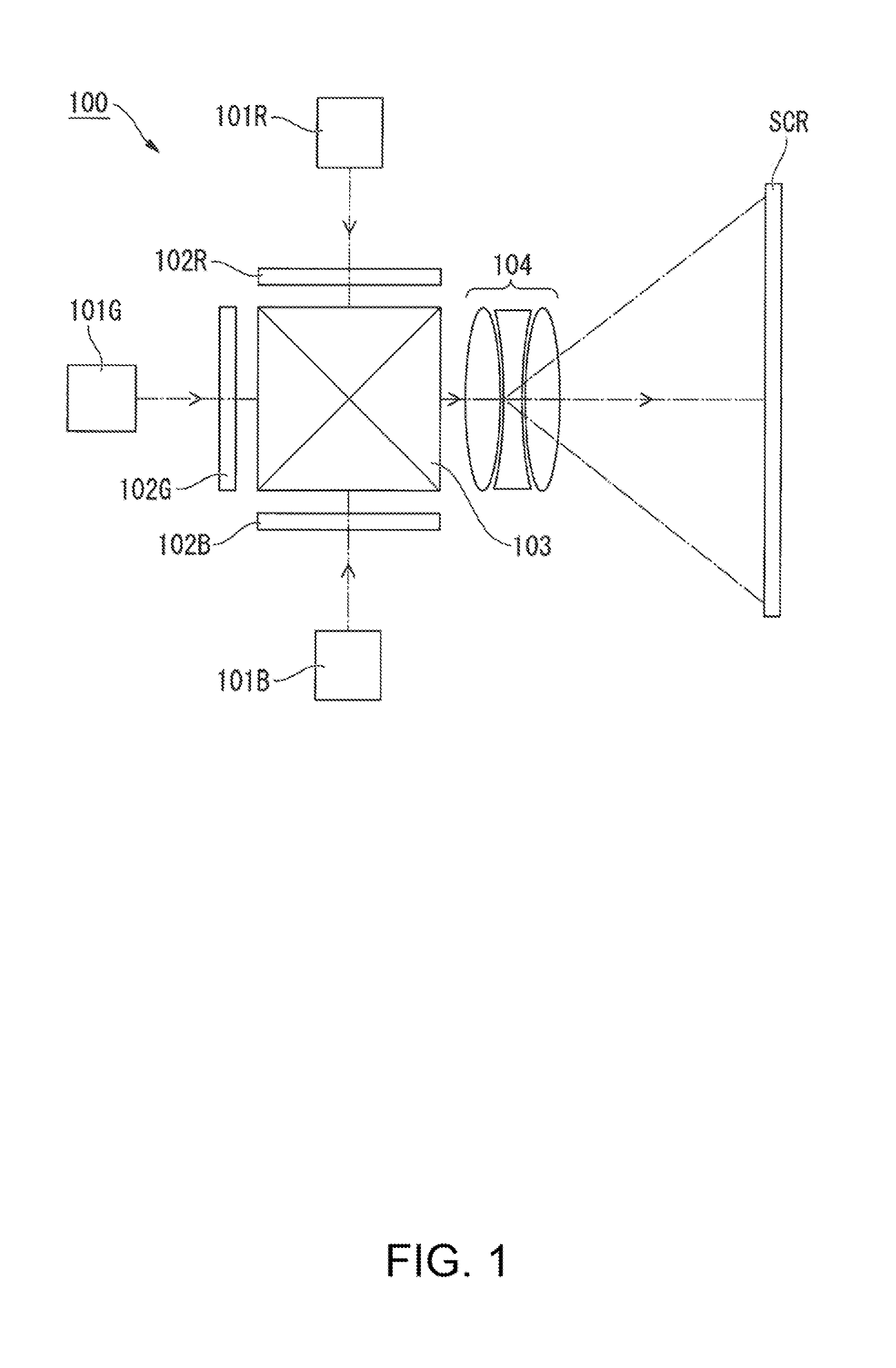
[0028]An example of a projector 100 shown in FIG. 1 will first be described.

[0029]FIG. 1 is a plan view showing a schematic configuration of the projector 100.

[0030]The projector 100 according to the present embodiment is a projection-type image display apparatus that displays color video images (still images) on a screen (projection receiving surface). A semiconductor laser (LD) or any other laser light source capable of emitting high-luminance, high-intensity light is used as a light source of an illuminator provided in the projector 100.

[0031]Specifically, the projector 100 includes illuminators 101R,...


PUM


Abstract

An illuminator includes a light source section having at least one solid-state light source, a multi-lens array provided in a position downs ream of a diffractive optical member and having a plurality of lenses, and a superimposing system provided in a position downstream of the multi-lens array. The diffractive optical member divides light from the light source section into a plurality of sub-light fluxes corresponding to the plurality of lenses. Each of the plurality of sub-light fluxes is incident on a corresponding lens. The plurality of sub-light fluxes having passed through the multi-lens array are superimposed on one another on an illumination receiving region through the superimposing system.

Description

BACKGROUND[0001]1. Technical Field[0002]The present invention relates to an illuminator and a projector.[0003]2. Related Art[0004]A projector is an apparatus in which a light modulator modulates light outputted from a light source section in accordance with image information and a projection lens enlarges and projects the resultant image. In recent years, as a light source in an illuminator used in such a projector, a semiconductor laser (LD) or any other laser light source that produces high-luminance, high-intensity light has received attention.[0005]To achieve a projector including an illuminator formed of such a laser light source, there is a known technology using a diffractive optical element to reduce the degree of interference fringes (see JP-A-2012-9872, for example).[0006]In the illuminator described above, however, any variation in the position of the mounted laser light source or collimator lens undesirably shifts the direction of the principal ray of light incident from...

Claims


Application Information

Patent Timeline
IPC IPC(8): G03B21/20F21V33/00G03B21/14F21V13/02
CPCG03B21/2033F21V13/02F21W2131/30G03B21/142F21Y2101/02F21V33/0052G03B21/2013G03B21/208F21Y2115/10G02B5/203G02B27/0961
Inventor AKIYAMA, KOICHI
Owner SEIKO EPSON CORP
Why Eureka
Try Eureka