Crank arm
a crank arm and crank arm technology, applied in the direction of force/torque/work measurement apparatus, cycle equipment, instruments, etc., can solve the problems of increasing manufacturing costs and/or manufacturing time of crank arms
- Summary
- Abstract
- Description
- Claims
- Application Information
AI Technical Summary
Benefits of technology
Problems solved by technology
Method used
Image

Examples
first embodiment
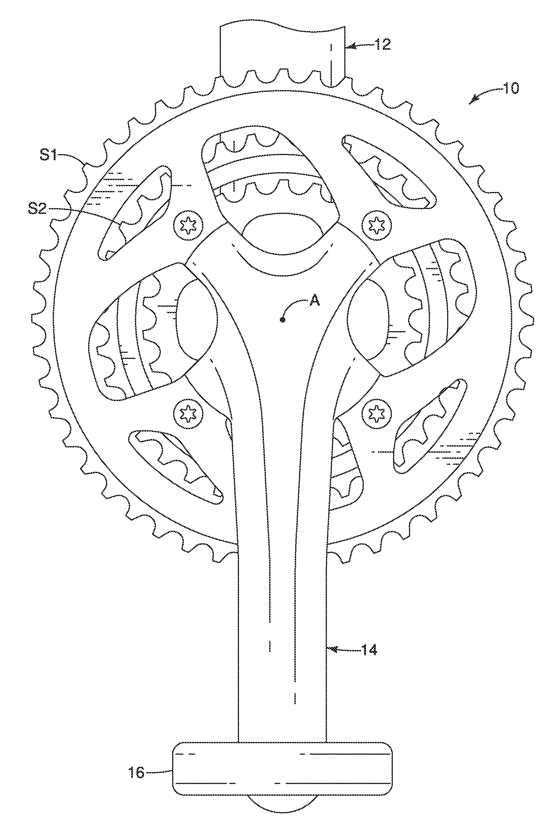
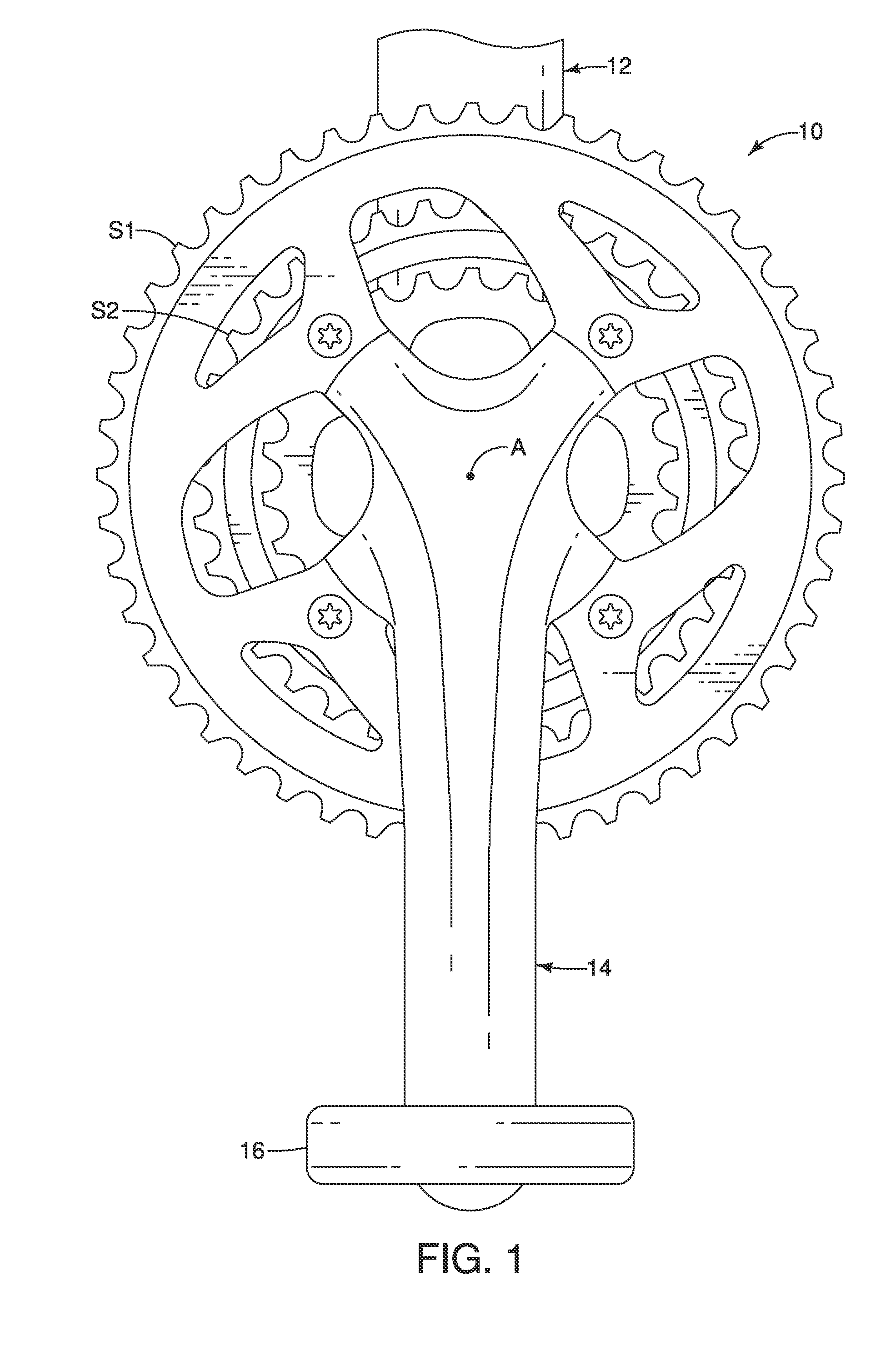
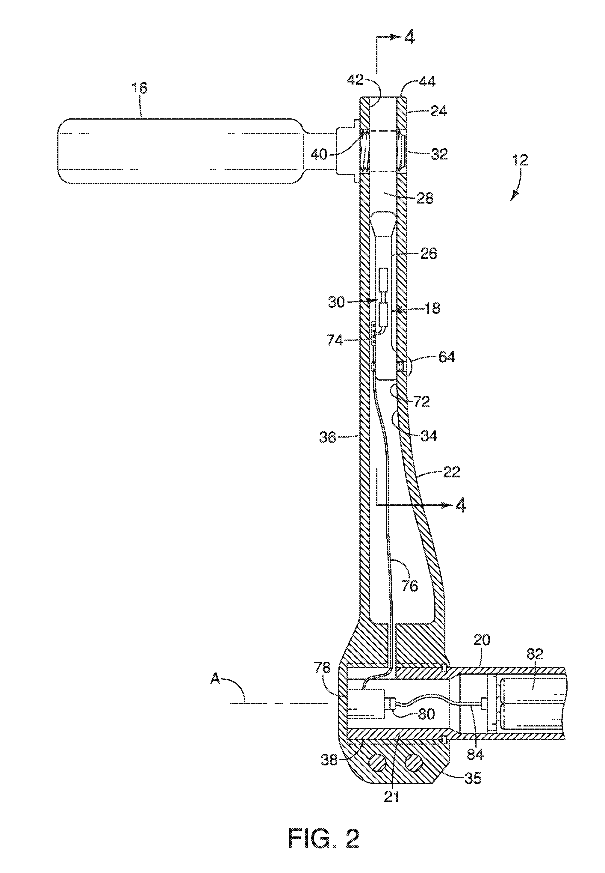
[0043]Referring initially to FIG. 1, a crank axle assembly 10 for a bicycle or a bicycle fitting device, or any other suitable device is illustrated. A concept of bicycle is including stationery bicycle. The crank axle assembly 10 has a first (left) crank arm 12 and a second (right) crank arm 14 in accordance with a The free ends of the crank arms 12 and 14 are each provided with a pedal 16. As is understood, user applies a pedaling force on the pedals 16 and then this force may be transmitted to the crank arms 12 and 14 for moving a chain (not shown) to propel the bicycle in a conventional manner or to move a resistance device (such as a wheel) in a bicycle fitting device. As explained hereinafter, the crank axle assembly 10 is provided with an input force converting apparatus 18 that detects a pedaling force to provide information (e.g., power transmitted to the crank axle assembly 10), which can be conveyed to the rider and / or used by various electronic components.
[0044]As illus...
second embodiment
[0064]the present invention showing first crank arm 12′ is illustrated in FIGS. 10 and 11. In this embodiment, the input force converting apparatus 18′ includes a sensor support member 26′ with a first axle support portion 86 and a second axel support portion 88. In this embodiment, the first axle support portion 86 of the sensor support member 26′ is configured to support a crank axle 20 as the axle. Moreover, the second axel support portion 88 of the sensor support member 26′ is configured to support the pedal axel 32. Accordingly, and the second axel support portion 88 is configured to support a pedal axle as the axle, and the first axel support portion is further configured to support the crank axle 20 as another axle, as shown in FIG. 11. However, if desired, the sensor support member 26′ may be attached to the crank axel at a first end and to the inside of the crank arm using bolts 64 at another portion (such as a second end). That is, the support member 26′ does not necessari...
PUM
| Property | Measurement | Unit |
|---|---|---|
| pedaling force | aaaaa | aaaaa |
| flexible | aaaaa | aaaaa |
| stiffness | aaaaa | aaaaa |
Abstract
Description
Claims
Application Information
 - R&D
- Intellectual Property
- Life Sciences
- Materials
- Tech Scout
- Unparalleled Data Quality
- Higher Quality Content
- 60% Fewer Hallucinations
Browse by: Latest US Patents, China's latest patents, Technical Efficacy Thesaurus, Application Domain, Technology Topic, Popular Technical Reports.
© 2025 PatSnap. All rights reserved.Legal|Privacy policy|Modern Slavery Act Transparency Statement|Sitemap|About US| Contact US: help@patsnap.com