Tape-like member, tape cartridge, and tape printing device
- Summary
- Abstract
- Description
- Claims
- Application Information
AI Technical Summary
Benefits of technology
Problems solved by technology
Method used
Image

Examples
third embodiment
Print Tape of Third Embodiment
[0069]Next, a print tape 10B according to a third embodiment will be described with reference to FIG. 5. In the third embodiment, different parts from the first embodiment will be mainly described.
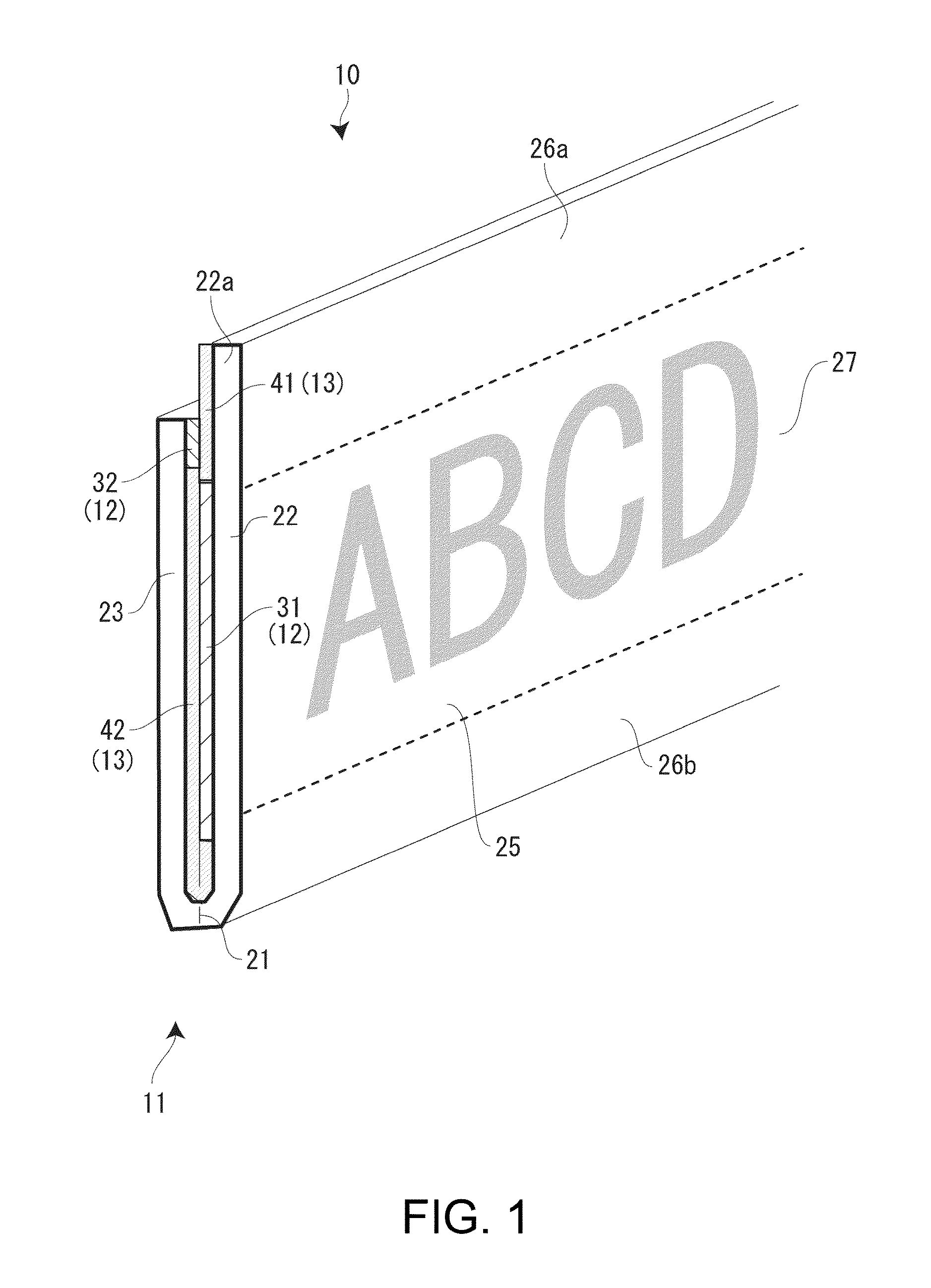
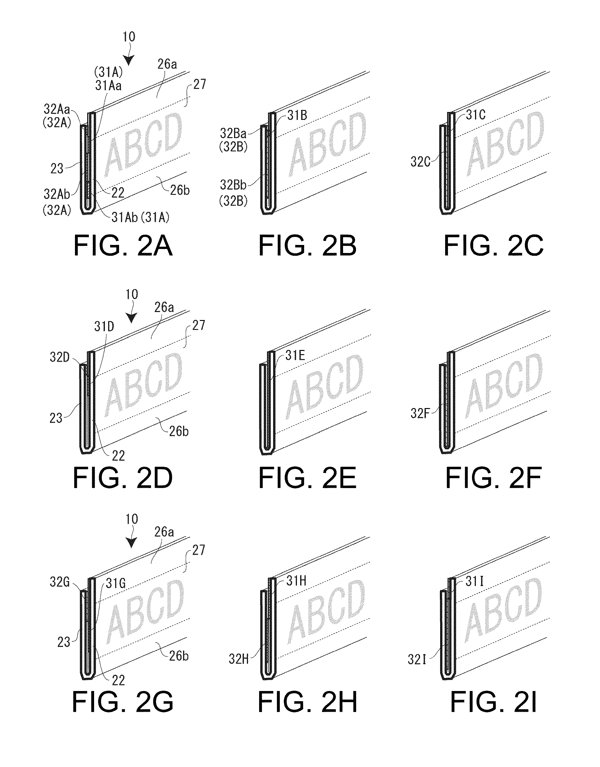
[0070]As shown in FIG. 5, in this embodiment, too, the print tape 10B includes a two-fold tape main body 11, an adhesive layer 12 applied on the inner side of the tape main body 11, and a release agent layer 13 applied to the other parts than the adhesive layer 12.
[0071]The tape main body 11 has a print piece 22 and a non-print piece 23. However, in the tape main body 11 of the third embodiment, the print piece 22 is formed to be narrower than the non-print piece 23. That is, the width end part of the non-print piece 23 protrudes with respect to the print piece 22, and this width end part forms a finger hook 23a. Again, in this case, as in the first embodiment, the adhesive layer 12 includes a first adhesive layer 31 applied on the inner side of the print piec...
first embodiment
Tape Cartridge of First Embodiment
[0076]Next, a tape cartridge 70 equipped with the print tape 10 (10A, 10B) will be described.
[0077]FIG. 7 is a partly cut perspective view of the tape cartridge 70 according to the first embodiment. As shown in FIG. 7, the tape cartridge 70 has a cartridge case 71 including a top case 72 and a bottom case 73, and also has the print tape 10, an ink ribbon 75 and a platen roller 76 accommodated in the cartridge case 71.
[0078]The top case 72 and the bottom case 73 are resin-molded products having the same “L”-shaped contour. The top case 72 is made of a transparent resin (transparent to visible rays) so that the inside of the cartridge case 71 is visible from the front of the top case 72. An indication label 81 showing attribute information of the print tape 10 in the form of letters is pasted on the front of the cartridge case 71. On the indication label 81, for example, the tape width of the print tape 10 is shown as a number, and the type of the pri...
second embodiment
Tape Cartridge of Second Embodiment
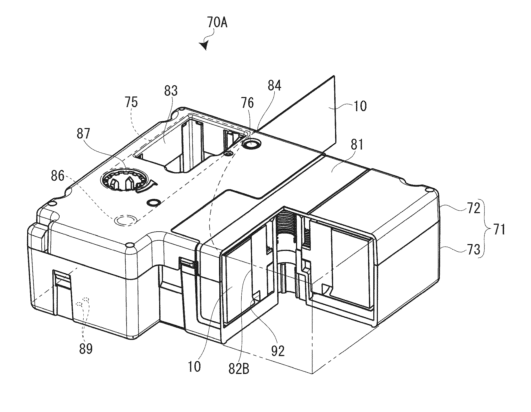
[0082]Next, a tape cartridge 70A according to the second embodiment will be described with reference to FIG. 8. In the second embodiment, different parts from the first embodiment will be mainly described. This tape cartridge 70A, too, is equipped with the print tape 10 (10A, 10B). Only a tape core 82B has a different configuration from the first embodiment.
[0083]The tape core 82B of the second embodiment is formed in a cylindrical stepped form. That is, in the tape core 82B, an end winding site 92 on the side of the fold 21 on the print tape 10 is formed in a stepped form with a smaller diameter than the other winding sites. In this case, too, the print tape 10 is wound parallel to the tape core 82B.
[0084]As described above, according to the tape cartridges 70, 70A of the embodiments, the end winding sites 91, 92 of the tape cores 82A, 82B have the special shapes, considering that the part of the fold 21 on the print tape 10 is thick. Therefore, t...
PUM
| Property | Measurement | Unit |
|---|---|---|
| Diameter | aaaaa | aaaaa |
| Shape | aaaaa | aaaaa |
| Width | aaaaa | aaaaa |
Abstract
Description
Claims
Application Information
 - R&D Engineer
- R&D Manager
- IP Professional
- Industry Leading Data Capabilities
- Powerful AI technology
- Patent DNA Extraction
Browse by: Latest US Patents, China's latest patents, Technical Efficacy Thesaurus, Application Domain, Technology Topic.
© 2024 PatSnap. All rights reserved.Legal|Privacy policy|Modern Slavery Act Transparency Statement|Sitemap