Particles having a sinterable core and a polymeric coating, use thereof, and additive manufacturing method using the same

a technology of sinterable core and polymeric coating, applied in the direction of manufacturing tools, inks, transportation and packaging, etc., can solve problems such as affecting product quality

Pending Publication Date: 2020-01-02
HOGANAS AB
View PDF0 Cites 3 Cited by
  • Summary
  • Abstract
  • Description
  • Claims
  • Application Information

AI Technical Summary

Benefits of technology

[0002]Manufacturing by 3D printing is one step closer to having finished goods directly from digital data, eliminating time staking and costly tooling. Since it is an additive manufacturing process it does not generate waste as is common in subtractive machining. Various objects can be manufactured from the same stock of powder, little labor and skills are required for multi-part designs, and full creation by digital information reduces risk for human error.
[0011]It is an object of the present invention to provide means for increasing the Green Strength of a green part obtained during a 3DP process.
[0012]It is a further object of the present invention to provide particles suitable for use in a 3DP process that allow increasing the Green Strength beyond the Green Strength currently obtainable, preferably without requiring further adaptations to the 3DP process.
[0013]It is a further object of the present invention to provide particles suitable for use in a 3DP process that allow adjusting the Green Strength of the green part by increasing the amount of binder composition / ink, thereby increasing the versatility of the particles.
[0014]It is a further object of the present invention to provide particles suitable for use in a 3DP method that have protection against outer influences and are less prone to surface reactions such as oxidation, without the need for deprotection steps prior to the use of the particles.

Problems solved by technology

Each method has its own advantages and disadvantages, in particular with regard to the obtained resolution, the materials that can be employed, manufacturing time, equipment costs, etc.
This implies, as one example, that the viscosity of the binder composition / ink can remain unaltered, as an increase or decrease in viscosity are expected to cause problems with currently used inkjet heads and may impair product quality.

Method used


Image

  • Particles having a sinterable core and a polymeric coating, use thereof, and additive manufacturing method using the same

Examples


examples 10-13

[0112]Polymer Particles C and D were prepared in a similar manner as Polymer Particles A and B, except that the amount of PVP (Mw of 25,000) added to the coating solutions A / B was increased to reach a theoretical PVP content of not 1% by weight (as for Particles A and B), but of 2% by weight. The amount of 316L stainless steel particles was thus reduced to 980 g.

[0113]Additionally, the mixing process was altered by using a “Cyclomix high shear impact mixer”, (Hosokava Micron B.V.). The mixer has a capacity of around 10 kg, vacuum can be applied during mixing and heating up to 150° C. of the mixing chamber is possible. The rotation speed can be varied between 60-1750 rpm. For Particles D using coating solution B′, not only the amount of PVP was increased as compared to coating solution B, but also surfactant content was increased to 2,50 (Tego Wet), and an additional surfactant was added in an amount of 2.5% (BYK DYNWET™ 800 N, an alcohol alkoxylate).The exact compositions of the coa...


PUM

PropertyMeasurementUnit
diameteraaaaaaaaaa
diameteraaaaaaaaaa
temperatureaaaaaaaaaa

Abstract

Particles each having a sinterable core and a polymeric coating on at least a part of the core, wherein the polymeric coating includes a polymer that can be removed via decomposition by heat, catalytically or by solvent treatment, and wherein the polymeric coating is present in an amount of 0.10 to 3.00% by weight, relative to the total weight of the particles, as well as the use of these particles in an additive manufacturing process such as a powder bed and inkjet head 3D printing process. The particles and the process are able to provide a green part having improved strength and are thus suitable for the production of delicate structures which require a high green strength in order to minimize the risk of structural damage during green part handling.

Description

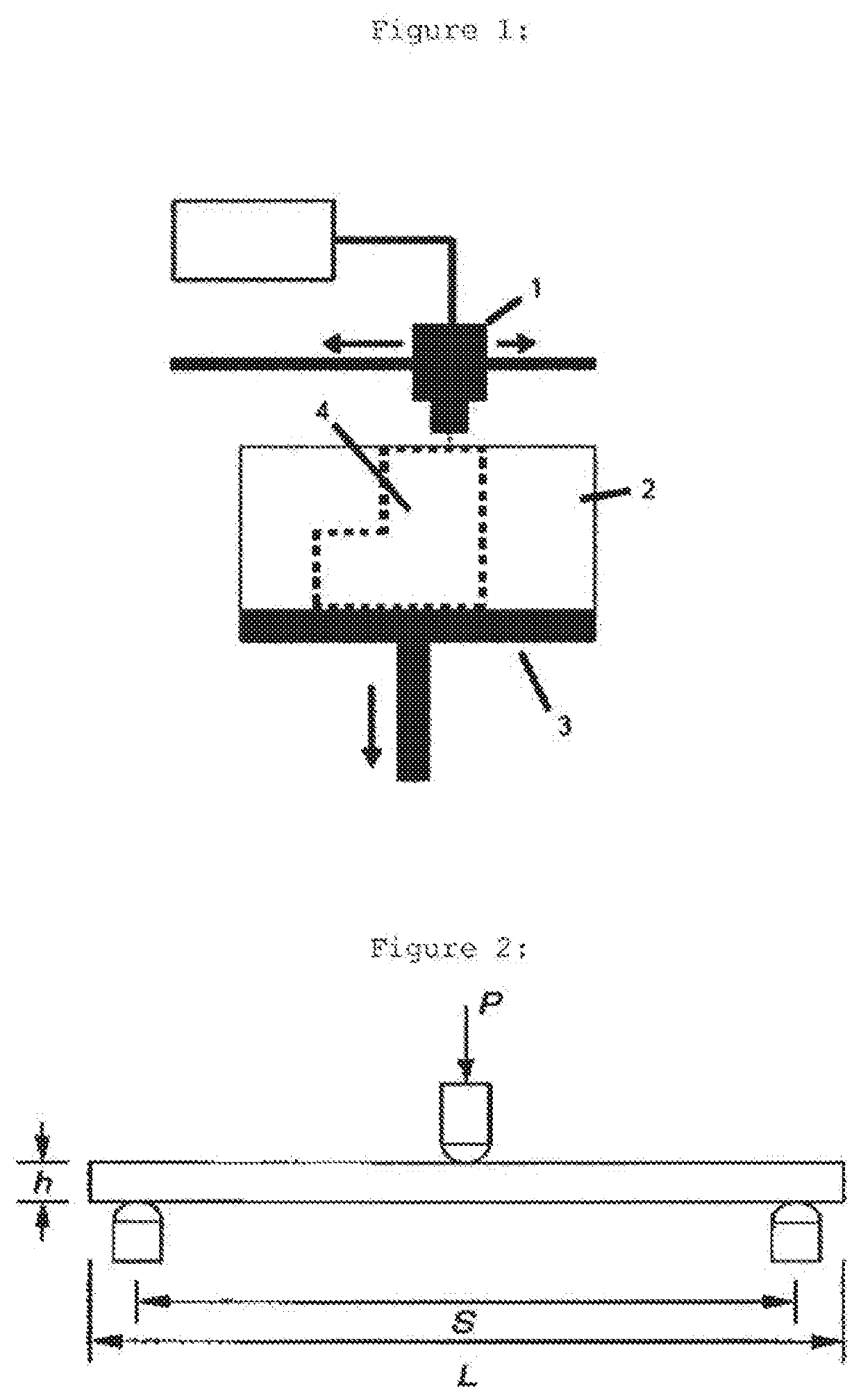
[0001]In today's industries the fabrication of complicated geometrical shapes are typically made with the aid of computer aided design, (CAD). With Solid Freeform Fabrication, (SFF) also called rapid prototyping, (RP) one can utilize CAD models to create physical objects through a layer by layer technique, where a highly intricate 3D model becomes segmented into thin 2D slices and thereby feasible to be constructed with the aid of 3D printers.[0002]Manufacturing by 3D printing is one step closer to having finished goods directly from digital data, eliminating time staking and costly tooling. Since it is an additive manufacturing process it does not generate waste as is common in subtractive machining. Various objects can be manufactured from the same stock of powder, little labor and skills are required for multi-part designs, and full creation by digital information reduces risk for human error.[0003]Today, many different manufacturing methods are employed, including Fused Depositi...

Claims


Application Information

Patent Timeline
Patent Type & Authority Applications(United States)
IPC IPC(8): B22F1/00B22F3/00B28B1/00B33Y10/00B33Y70/00C09D11/037C09D11/106C09D11/322B22F1/102
CPCC09D11/322B22F1/0062B33Y70/00C09D11/106B33Y10/00B28B1/001C09D11/037B22F3/008C04B35/62802C04B35/63424C04B35/63444C04B35/63456C04B35/6346C04B35/63464C04B35/63488C04B35/638C04B2235/5436C04B2235/6026C04B2235/61B22F10/10B22F1/102C04B35/63408B33Y50/02C01P2004/51C01P2004/61Y10T428/2998
Inventor NILSSON, SOFIAFERRAND DRAKE DEL CASTILLO, RAGNARAHLIN, ÅSA
Owner HOGANAS AB
Why Eureka
Try Eureka