Correction method for solid-state detectors and solid-state detector

a detector and solid-state technology, applied in the direction of instruments, x/gamma/cosmic radiation measurement, optics, etc., can solve the problems of corrupted object representations and artifacts, x-ray image discontinuity, etc., to save time and money for expensive processing units, simple and straightforward correction, and discontinuity to be corrected especially easily

Inactive Publication Date: 2008-12-23
SIEMENS HEALTHCARE GMBH
View PDF4 Cites 0 Cited by
  • Summary
  • Abstract
  • Description
  • Claims
  • Application Information

AI Technical Summary

Benefits of technology

[0008]In accordance with an embodiment of the invention, the second plate element is displaced in relation to the first plate element and the discontinuity produced by this is removed at least partly by an image processing correction from the part of the digital raw x-ray image which is formed from the pixel elements of the displaced second plate element. The fact that the entire raw x-ray image is not corrected, but only a part of it, advantageously allows computing effort and thereby also time and money for expensive processing units to be saved.
[0009]In an advantageous manner for a simple and straightforward correction, raw values of the pixel elements read out of the displaced second plate element are shifted by at least one pixel element length in the direction of the displacement. This enables the discontinuity to be corrected especially easily from the raw x-ray image.
[0011]In an advantageous manner the displacement is measured and determined before the pixel matrix is read out. This makes data about the displacement available quickly and easily for the subsequent correction process. An especially advantageous method of measuring and determining the displacement is provided by the pixel matrix and thereby the displacement being optically scanned. In accordance with a further embodiment of the invention the displacement is determined by comparing the raw x-ray image of a known object, especially of a network grid, with an uncorrupted image of the known object. The displacement can for example be determined when the solid-state detector is being commissioned or during a calibration. Subsequently the displacement is expediently stored in a memory unit, so that it is able to be retrieved at any time if required.

Problems solved by technology

When the plates are being glued together however, it is generally not possible for technical reasons to avoid a displacement of the different a-Si plates in relation to each other.
The displacement results in a discontinuity in the raw x-ray image read out.
This in its turn leads to corrupted object representations and artifacts.

Method used


Image

  • Correction method for solid-state detectors and solid-state detector
  • Correction method for solid-state detectors and solid-state detector
  • Correction method for solid-state detectors and solid-state detector

Examples


Embodiment Construction

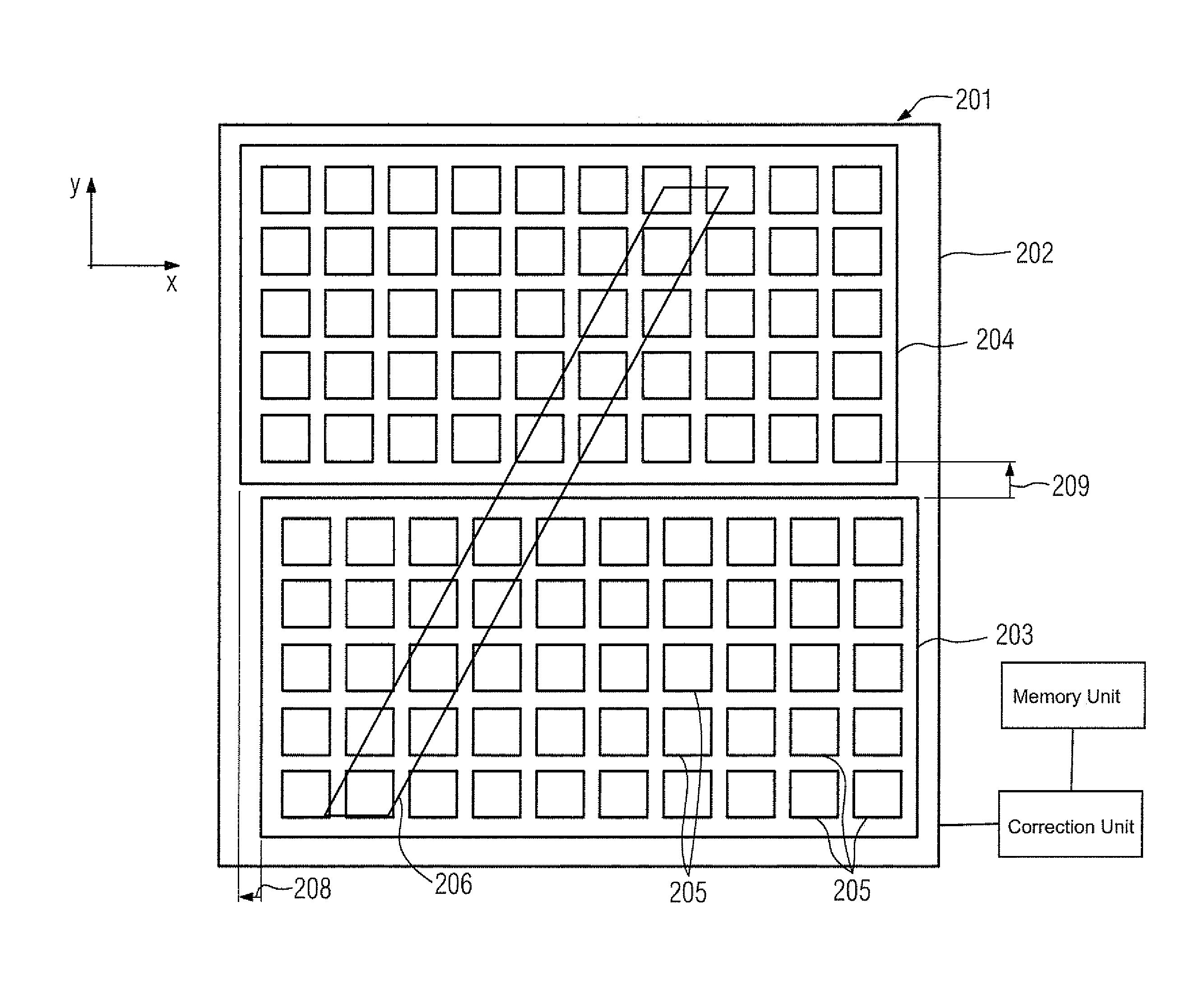
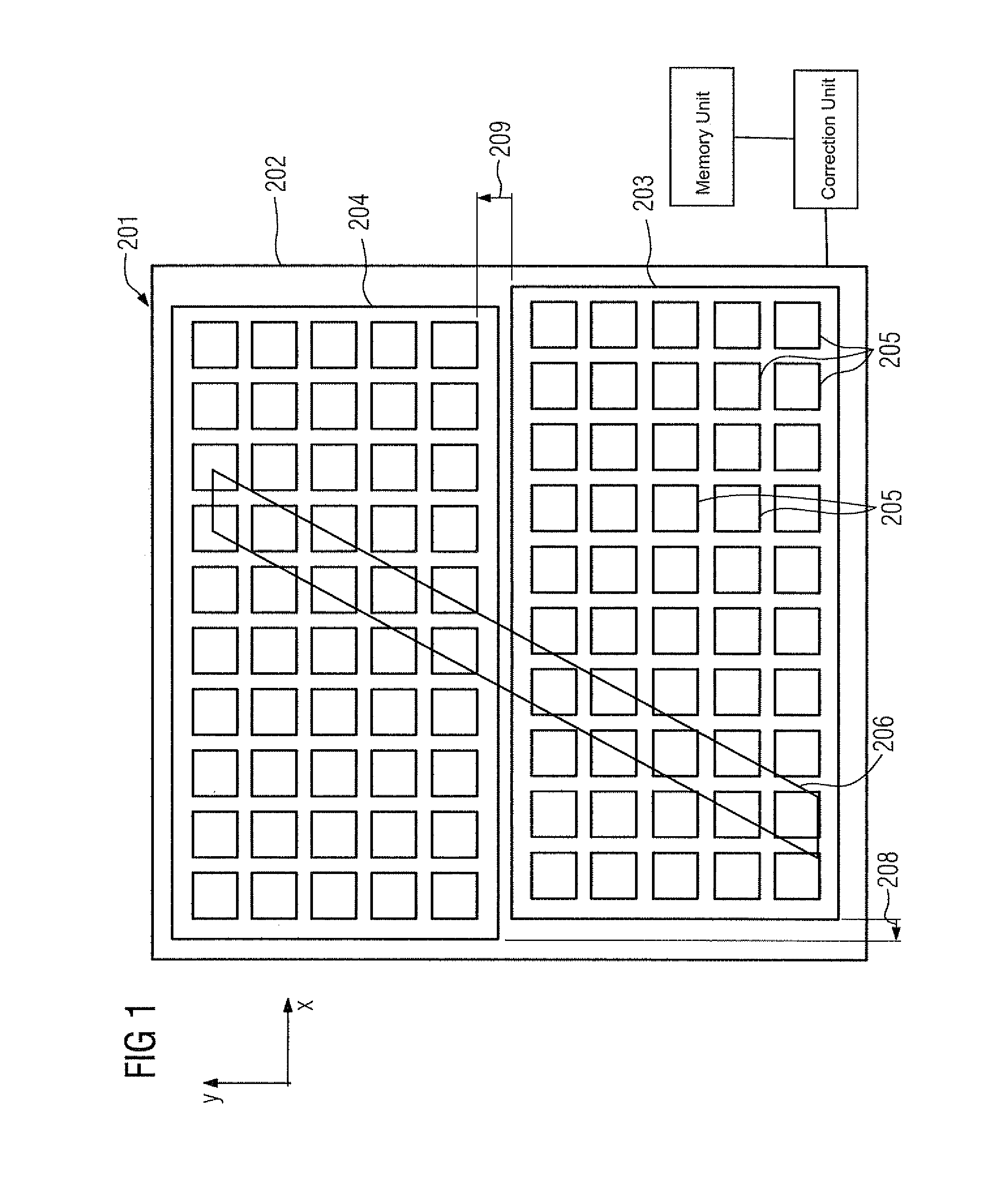
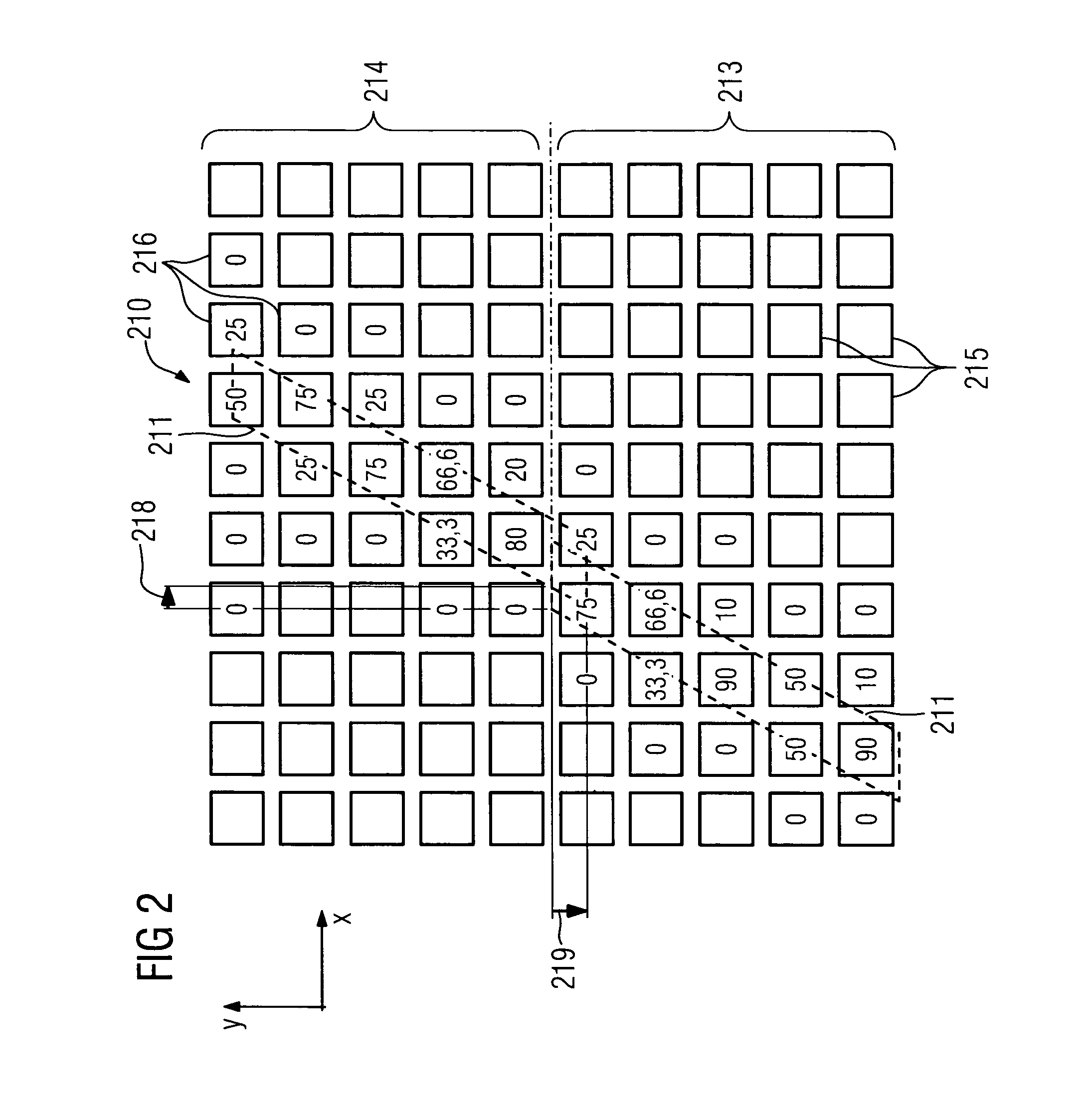
[0018]FIG. 1 shows a pixel matrix 201 of a solid-state detector, which is made up of a first plate element and a second plate element, with both elements being glued to a glass substrate 202 and thereby being arranged in one plane. The first plate element is advantageously formed from a first a-Si plate 204 and the second plate element from a second a-Si plate 203. Each a-Si plate 203; 204 consists of a finite number of square-shaped pixel elements 205. The pixel elements measure raw values, which can for example be gray values, and which can then for example be displayed on a monitor as a raw x-ray image 210.

[0019]The first a-Si plate 203 and the second a-Si plate 204 are arranged displaced relative to one another, or for simpler definition the second a-Si plate 204 is shifted from the first a-Si plate 203 by a displacement 208; 209. The displacement 208; 209 of the second a-Si plate 204 in relation to the first a-Si plate 203 has a first displacement component 208 which is directe...


PUM


Abstract

To guarantee a largely uncorrupted x-ray image for a solid-state detector with a pixel matrix featuring pixel elements comprising at least two plate elements arranged in one plane, whereby a first and a second plate element exhibit a displacement in relation to one another, a correction method is provided, whereby a digital raw x-ray image is read out from the pixel matrix and a discontinuity generated in the digital raw x-ray image by the displacement of the plate elements in relation to each other is removed at least partly from the image by an image processing correction. In accordance with an embodiment of the invention the second plate element has a displacement from the first plate element and the discontinuity generated is removed at least partly by an image processing correction from the section of the digital x-ray image which is formed by the pixel elements of the displaced second plate element.

Description

CROSS REFERENCE TO RELATED APPLICATIONS[0001]This application claims priority of German application No. 10 2005 036 811.5 filed Aug. 4, 2005, which is incorporated by reference herein in its entirety.FIELD OF THE INVENTION[0002]The invention relates to a correction method for solid-state detectors and to a solid-state detector.BACKGROUND OF THE INVENTION[0003]X-ray detectors are known from x-ray imaging which are embodied as solid-state detectors for recording digital x-ray images of an object to be examined, in which x-ray radiation is converted by a scintillator or a direct converter layer into electrical charge and subsequently read out electronically by means of active pixel matrixes. Subsequently the imaging data representing the examination results is transmitted to an evaluation and display unit and further processed to generate the image (article entitled, “Flachbilddetektoren in the Röntgendiagnostik” (solid-state detectors in x-ray diagnosis) by M. Spahn, V. Heer, R. Freyt...

Claims


Application Information

Patent Timeline
Patent Type & Authority Patents(United States)
IPC IPC(8): H05G1/64
CPCG01T1/2928G03B42/02
Inventor FINKLER, KLAUSSPAHN, MARTIN
Owner SIEMENS HEALTHCARE GMBH
Why Eureka
Try Eureka