Injector sleeve installation tool and removal tool kit

a technology for injector sleeves and installation tools, which is applied in the direction of manufacturing tools, machines/engines, mechanical equipment, etc., can solve the problems of leakage, sleeve replacement, and cost in time and money, and achieve the effect of costing in time and money

Active Publication Date: 2017-11-28
WHITAKER TOOLS
View PDF15 Cites 0 Cited by
  • Summary
  • Abstract
  • Description
  • Claims
  • Application Information

AI Technical Summary

Benefits of technology

[0006]An injector sleeve is used to seal each of the cavities in the top of a cylinder head or heads of a diesel. The sleeve maintains a clean environment within the cylinder head cavity by keeping external debris outside. The sleeve is generally made of brass or bronze and is sized to be pressed into the cavity. If the sleeve fails, leaks can occur and the sleeve must be replaced. This can require removal of the cylinder head, which is costly in terms of time and money. A huge savings is realized if the sleeve or sleeves can be removed without the removal of the cylinder head. The present invention is a tool which makes sleeve removal possible without removing the cylinder head.
[0007]A sleeve installation tool is disclosed herein which is used to fasten an injector sleeve within a diesel cylinder head. Further, a sleeve removal tool is disclosed herein used for removing an injector sleeve from the cylinder head of a diesel engine without the extra labor and cost of removing the entire head from the diesel engine.
[0013]Experience has shown that two or three turns of thread into the sleeve are sufficient to pull the sleeve. One superior aspect of this design is that one can turn in more threads if required. Also, the pulling method is the even, central and straight thrust provided when the loose nut is tightened against the flat washer bearing surface member. This is believed to be more stable and powerful than that of tools that use the uneven strikes of a slide hammer.
[0014]A major feature of the sleeve removal tool is that the sleeves are removed without having to remove the engine from the vehicle, saving time, labor, expense, and increasing safety.The Injector Sleeve Installation Tool
[0015]As discussed above, one type of injector sleeve is configured to easily slip into place within the cylinder head and must then be fastened tightly in place. A sleeve installation tool is used to expand a portion of the sleeve to tightly fix the sleeve within the cylinder. The injector sleeve is a hollow brass or bronze shell which is roughly cylindrical with two open ends. The cylinder is roughly tapered in steps with the opening at the large end being larger than the opening at the small end. The installation tool is a two part roughly cylindrical mandrel which is longer than the injector sleeve. The first part of the mandrel is an outer shell. The distal end of the outer shell of the mandrel is divided into axially parallel sections that can spread apart and thus expand the diameter of the shell. The second part of the mandrel is a rod with external threads and a bolt head at one end and which is tapered in selected positions down the length of the rod. When the rod is forced down into the outer shell, the sections of the outer shell expand radially outward. The end of the outer shell which is opposite of the end with the expanding sections has internal threads. The tapered end of the rod is inserted into the interior threaded end. The rod further pushed into the outer shell until the external threads of the rod can be threaded into the internal threads of the outer shell. Thus, as the rod is pulled into the outer shell by twisting the bolt head, the tapered sections of the rod cause the expandable section of the outer shell to extend and expand radially outward. With the expandable sections of the outer shell inserted into the injector sleeve, the sleeve is also expanded, thus resulting in a press fit of the sleeve within the cylinder head.The Injector Sleeve Kit

Problems solved by technology

If the sleeve fails, leaks can occur and the sleeve must be replaced.
This can require removal of the cylinder head, which is costly in terms of time and money.

Method used


Image

  • Injector sleeve installation tool and removal tool kit
  • Injector sleeve installation tool and removal tool kit
  • Injector sleeve installation tool and removal tool kit

Examples


Embodiment Construction

[0045]In accordance with the present invention, a tool is disclosed herein used for removing an injector sleeve from the cylinder head of a diesel engine without the extra labor and cost of removing the entire head from the diesel engine.

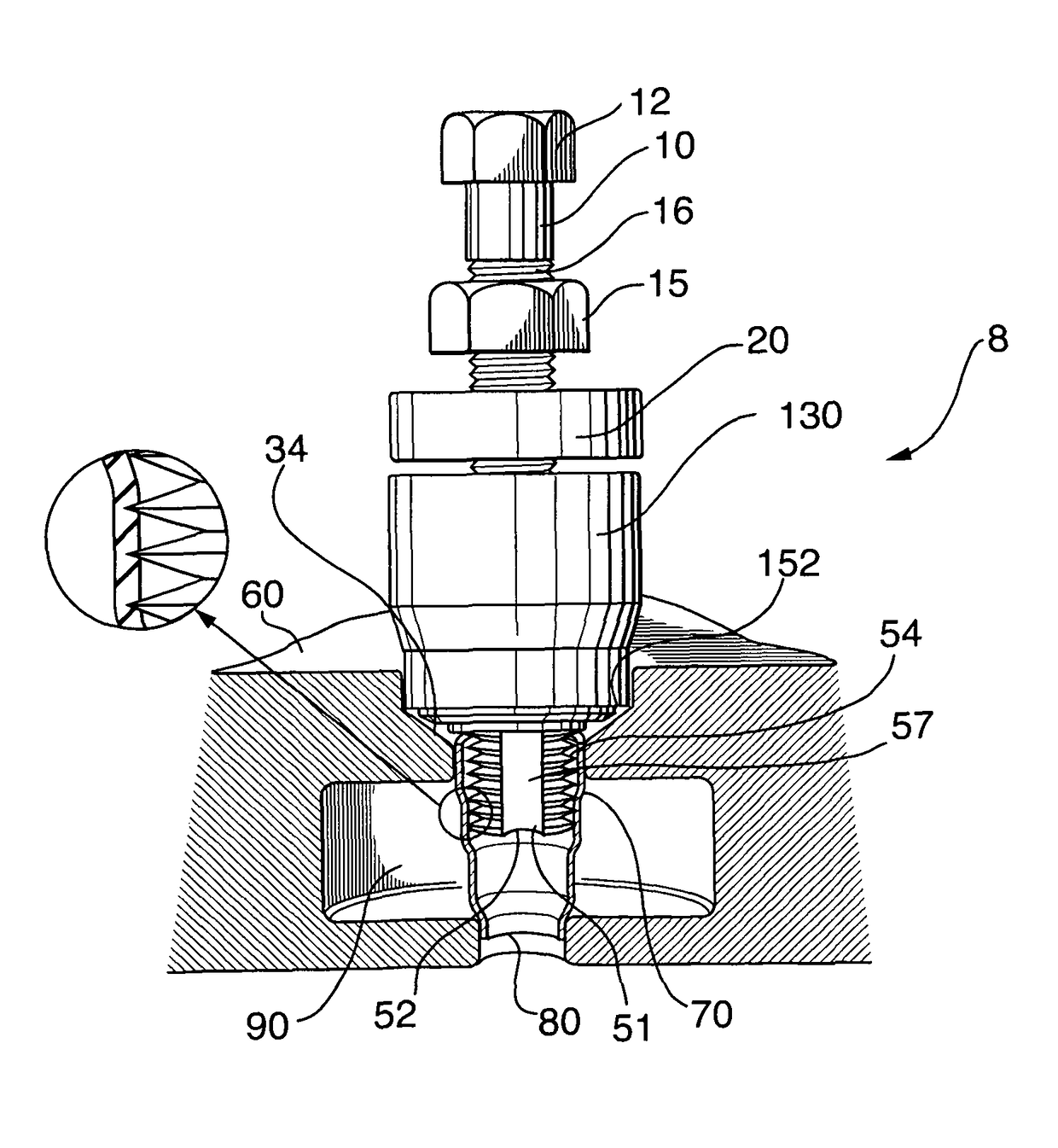
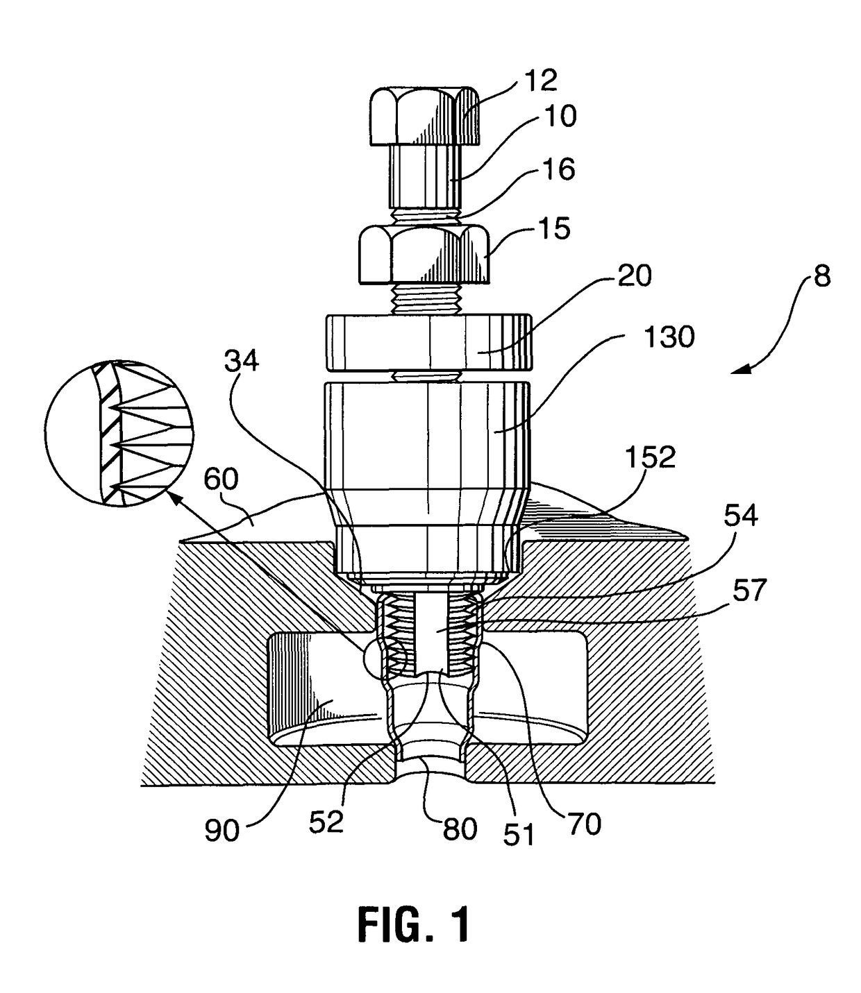
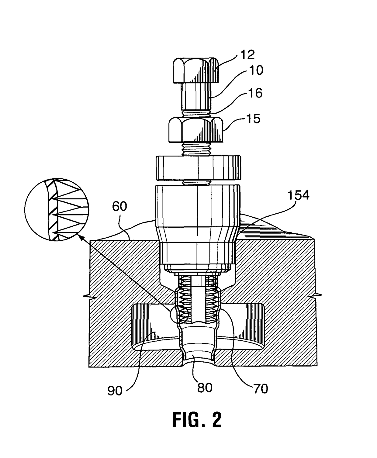
[0046]FIGS. 1-4 show the assembled tool 8 for removing an injector sleeve along with a portion of a cylinder head and described as follows. An axially movable threaded rotating extraction nut 15 is threaded onto a bolt 10 having a head 12 defining a holding means extending from a shaft having threads 16 at least along the distal end opposite the head 12. In the embodiment of FIG. 1, about one and one half inches of the threads 16 of bolt 10 extend through rotating non-ratcheting.

[0047]As seen in FIG. 11, tap 51 is rigidly attached to the bolt 10. The opposing distal end 52 of the tap 51 comprises a generally cylindrical threaded cutting head end portion 54 including threads which extend coaxially in a horizontal plane rather than an inclined plane s...


PUM

PropertyMeasurementUnit
lengthaaaaaaaaaa
inner diameteraaaaaaaaaa
outer diameteraaaaaaaaaa

Abstract

A tool for inserting and fastening a replacement injector sleeve in the cylinder head of a diesel engine. The tool is part of an injector sleeve tool kit which also includes an injector sleeve removal tool. The installation tool includes an expandable mandril which is inserted into the injector sleeve and expands a portion of the sleeve causing a press fit of the sleeve within the cylinder head. The sleeve removal tool includes a tap having a longitudinal body and a threaded cutting head at one end and a bolt having a head at the other end. An extraction nut is threaded onto the threaded shaft of the drive member followed by a bearing surface member such as a spacer. A hollow cylinder or support sleeve having an internal diameter greater than the injector sleeve to be removed and an external diameter less than the diameter of the sleeve bore includes a shoulder member.

Description

RELATED APPLICATIONS[0001]This application claims priority from and is a continuation in part of U.S. application Ser. No. 13 / 987,420 filed on Jul. 23, 2013 and U.S. Provisional Patent application Ser. No. 61 / 854,847 filed on May 2, 2013 both of which are incorporated by reference herein in their entirety.TECHNICAL FIELD[0002]The present invention relates to the field tools used to install and remove a typically brass or bronze injector sleeve from a cylinder head in a diesel engine. These sleeves are press fit into a bore in the head. After years of use the sleeves will loosen or begin to leak and need to be replaced.BACKGROUND OF THE INVENTION[0003]An injector sleeve removal tool is described in Applicant's U.S. Pat. No. 8,490,263 which issued on Jul. 23, 2013.[0004]Tools for the removal of injector sleeves have been described and patented in recent years. U.S. Pat. No. 5,784,783 by Carpenter for METHOD OF REMOVING AN INJECTOR SLEEVE issued on Jul. 28, 1998 claims a tool wherein o...

Claims


Application Information

Patent Timeline
Patent Type & Authority Patents(United States)
IPC IPC(8): B23P19/04B25B27/00B25B27/02B25B27/06
CPCB25B27/062B25B27/023B25B27/0035Y10T29/53883F02M61/14
Inventor WHITAKER, TONY
Owner WHITAKER TOOLS
Why Eureka
Try Eureka