Tactical Takedown Assist Tool

a technology of assist tools and semi-automatic firearms, which is applied in the direction of cartridge extractors, butts, weapons, etc., can solve the problems of complicated takedown issues, cumbersome negotiation of conventional takedown tools, and inability to solve basic problems

Inactive Publication Date: 2015-09-17
AZHOCAR FREDERICK STEVEN
View PDF28 Cites 16 Cited by
  • Summary
  • Abstract
  • Description
  • Claims
  • Application Information

AI Technical Summary

Benefits of technology

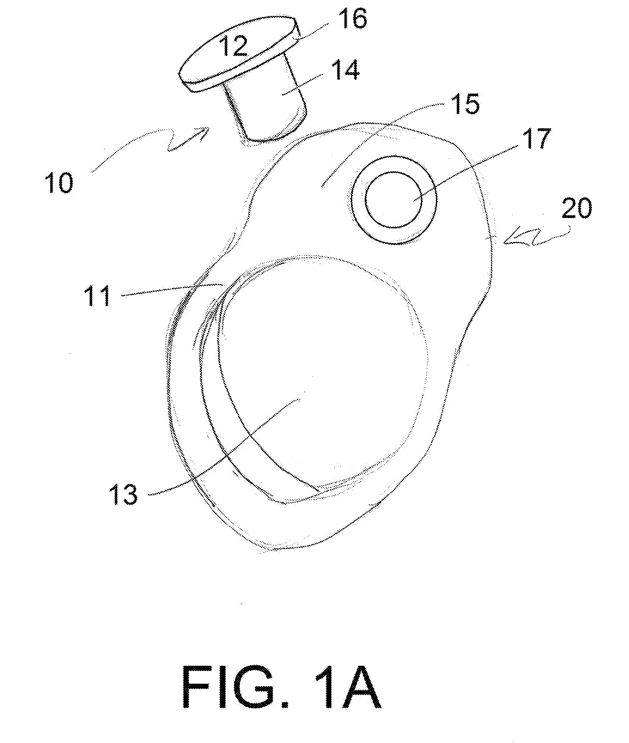
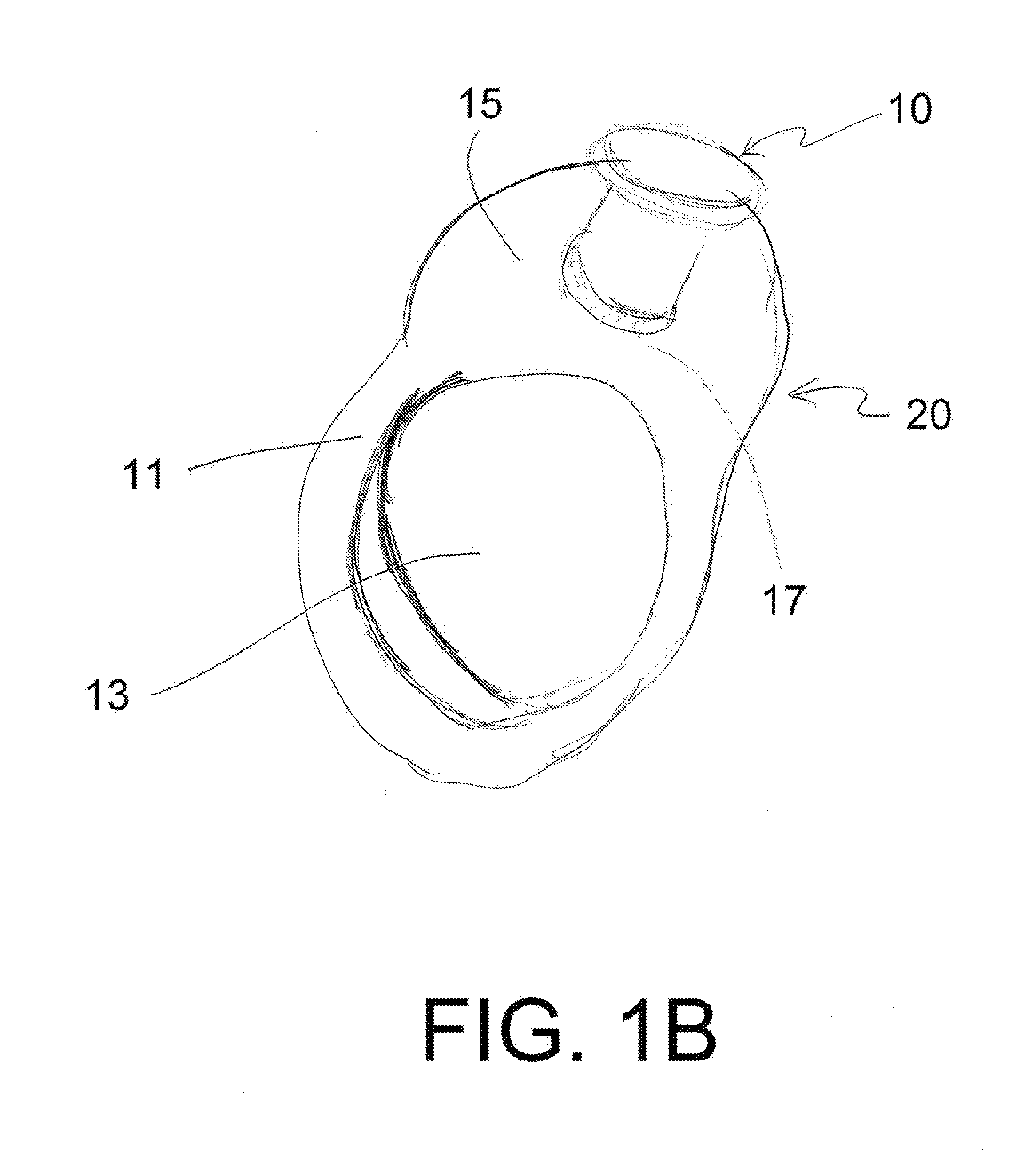
[0014]The invention is directed toward a magnetic takedown tool for removing pins from a takedown rifle. The magnetic takedown tool comprises a head portion and a body portion. The head portion has a first side and a second side opposite the second side, the first side and the second side forming a peripheral edge located between the first side and the second side. The peripheral edge contains one or more recessed tracks. Each of the one or more recessed tracks are configured to receive one or more securing elements. The body portion is connected to the second side of the head portion. The body portion is substantially cylindrical in shape. The longitudinal axis of body portion extends substantially perpendicular from the head portion. The body portion comprises a magnetic element. In another embodiment the second side of the head portion contains one or more recesses configured to permit one or more securing elements to access the one or more recessed tracks. In another embodiment the magnetic element is substantially cylindrical in shape. The longitudinal axis of the magnetic element is in substantial alignment with the longitudinal axis of the body portion. The magnetic element is connected to the body portion. In another embodiment the head portion further comprises a magnetic material.
[0015]The invention is also directed toward a firearm assembly for use in breaking down a takedown rifle. The firearm assembly comprises a magnetized takedown tool as described above and a docking station. The docking station comprises one or more securing elements and a recessed area. The docking station is configured to be removably secured to a takedown rifle. The magnetized takedown tool can be removably secured to the docking station by placing the body portion of the magnetized takedown tool within the recessed area of the docking station and positioning the one or more securing elements of the docking station within the one or more recessed tracks of the magnetized takedown tool. In another embodiment the docking station further comprises a magnetic element positioned within the recessed area of the docking station.
[0016]In another embodiment of the invention the assembly further comprises one or more swivels. The one or more swivels comprise a sling attachment, shaft connected to the sling attachment, and one or more bearings positioned at the base of the shaft. In this embodiment the docking station further comprises one or more receptacles. Each of the one or more receptacles define an internal opening for receiving the shaft of the sling swivel. The internal opening comprises one or more receptacle recesses for receiving the one or more bearings on the sling swivel.
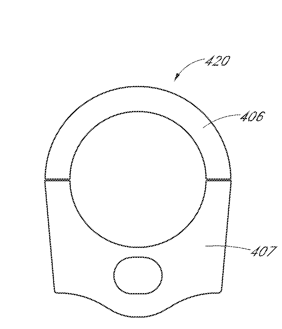
[0017]In another embodiment the docking station further comprises a central opening defining a space to receive a buffer tube of a firearm. Optionally, in another embodiment, the docking station comprises an upper portion and a lower portion. The upper portion and the lower portion may be removably secured together. When the upper portion is removably secured to the lower portion, the upper portion and the lower portion define a central opening defining a space to receive a buffer tube of a firearm.

Problems solved by technology

In the case of incidental takedowns, the fact that these rifles can be taken down and conveniently cased is quite incidental—accidental even—to the intent of their original design.
This has complicated the takedown issue in several ways.
However, basic problems continue to plague these takedown tools.
In practice, carrying a separate takedown assist tool in the field can present numerous challenges such as fumbling around while trying to pop the take down or pivot pin out.
In operation, conventional takedown tools are often cumbersome to negotiate while carrying a rifle and are nearly impossible to implement one handed.
Moreover, certain prior art takedown devices are tight and difficult to disengage, forcing the user to exert additional force disengage the pin, risking injury to the user and / or firearm.

Method used


Image

  • Tactical Takedown Assist Tool
  • Tactical Takedown Assist Tool
  • Tactical Takedown Assist Tool

Examples


Embodiment Construction

[0059]The claimed subject matter is now described with reference to the drawings. In the following description, for purposes of explanation, numerous specific details are set forth in order to provide a thorough understanding of the claimed subject matter. It may be evident, however, that the claimed subject matter may be practiced with or without any combination of these specific details, without departing from the spirit and scope of this invention and the claims. After reading this description it will become apparent to one skilled in the art how to implement the invention in various alternative embodiments and alternative applications. However, all the various embodiments of the present invention will not be described herein. It is understood that the embodiments presented here are presented by way of an example only, and not limitation. As such, this detailed description of various alternative embodiments should not be construed to limit the scope or breadth of the present inve...


PUM


Abstract

The invention is directed toward a magnetized takedown tool for removing pins from an assault rifle. The magnetic element of the magnetized takedown tool allows the tool to be removably secured to an assault rifle. In addition, the invention is directed toward a docking unit which may be removably secured to the assault rifle and to which the magnetized takedown tool can be removably secured during use.

Description

PRIORITY[0001]This application claims the benefit of U.S. Provisional Application No. 61 / 953,502, filed Mar. 14, 2014 and U.S. Provisional Application No. 62 / 056,417, filed Sep. 26, 2014.FIELD OF INVENTION[0002]This invention relates to semi-automatic firearms such as the M-16 / AR-15 rifle type; and more specifically, disclosed herein are tactical assist tools for use with semi-automatic firearms. In particular, a magnetized assembly for quick and easy takedown of a rifle is provided. In particular embodiments, the assembly includes attachment points for additional devices such as slings and the like.BACKGROUND OF INVENTION[0003]A rifle that can be taken apart so that its length is reduced by about half is easier to travel with, store, and pack. There are at least two types of takedown rifles: “incidental” takedowns and “intentional” takedowns. In the case of incidental takedowns, the fact that these rifles can be taken down and conveniently cased is quite incidental—accidental even—...

Claims


Application Information

Patent Timeline
Patent Type & Authority Applications(United States)
IPC IPC(8): F41A11/00
CPCF41A11/00F41A35/00F41C23/02
Inventor AZHOCAR, FREDERICK STEVEN
Owner AZHOCAR FREDERICK STEVEN
Why Eureka
Try Eureka