Optical route examination system and method

a technology of optical route and examination system, which is applied in the field of optical route examination system and method, can solve the problems of tracks shifting out of alignment with the original locations, damaged routes that are traveled by vehicles, and misalignment of tracks on which rail vehicles travel

Active Publication Date: 2015-09-24
GE GLOBAL SOURCING LLC
View PDF13 Cites 46 Cited by
  • Summary
  • Abstract
  • Description
  • Claims
  • Application Information

AI Technical Summary

Benefits of technology

The patent describes a method and system for optically examining a route, such as a track, by obtaining images of a segment of the route while the vehicle is moving along it and comparing them with a designated layout of the route. The system can identify differences between the images and the layout, which can indicate a misaligned segment of the route. The method can also include identifying foreign objects on the route and determining if they are transitory or persistent, and implementing appropriate mitigating actions based on this determination. The technical effect of this patent is to provide a reliable and efficient way to examine routes for foreign objects and ensure their removal, which can prevent accidents and improve safety.

Problems solved by technology

The technical problem addressed in this patent text is the need for a system to inspect rail tracks for misalignment, which can increase the risk of derailment and safety threats to passengers and nearby property. Current systems using visible markers require additional hardware and specialized rail vehicles, and may also result in human error. The patent seeks to provide a solution to this problem.

Method used


Image

  • Optical route examination system and method
  • Optical route examination system and method
  • Optical route examination system and method

Examples


Embodiment Construction

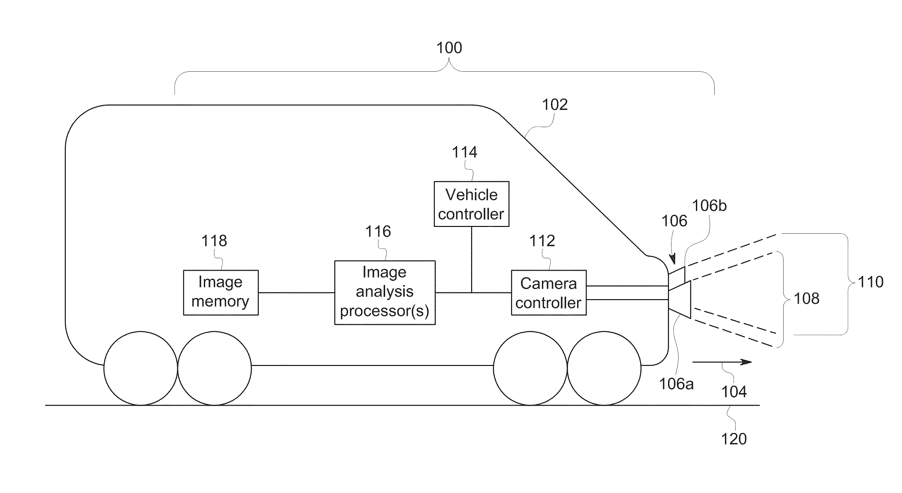
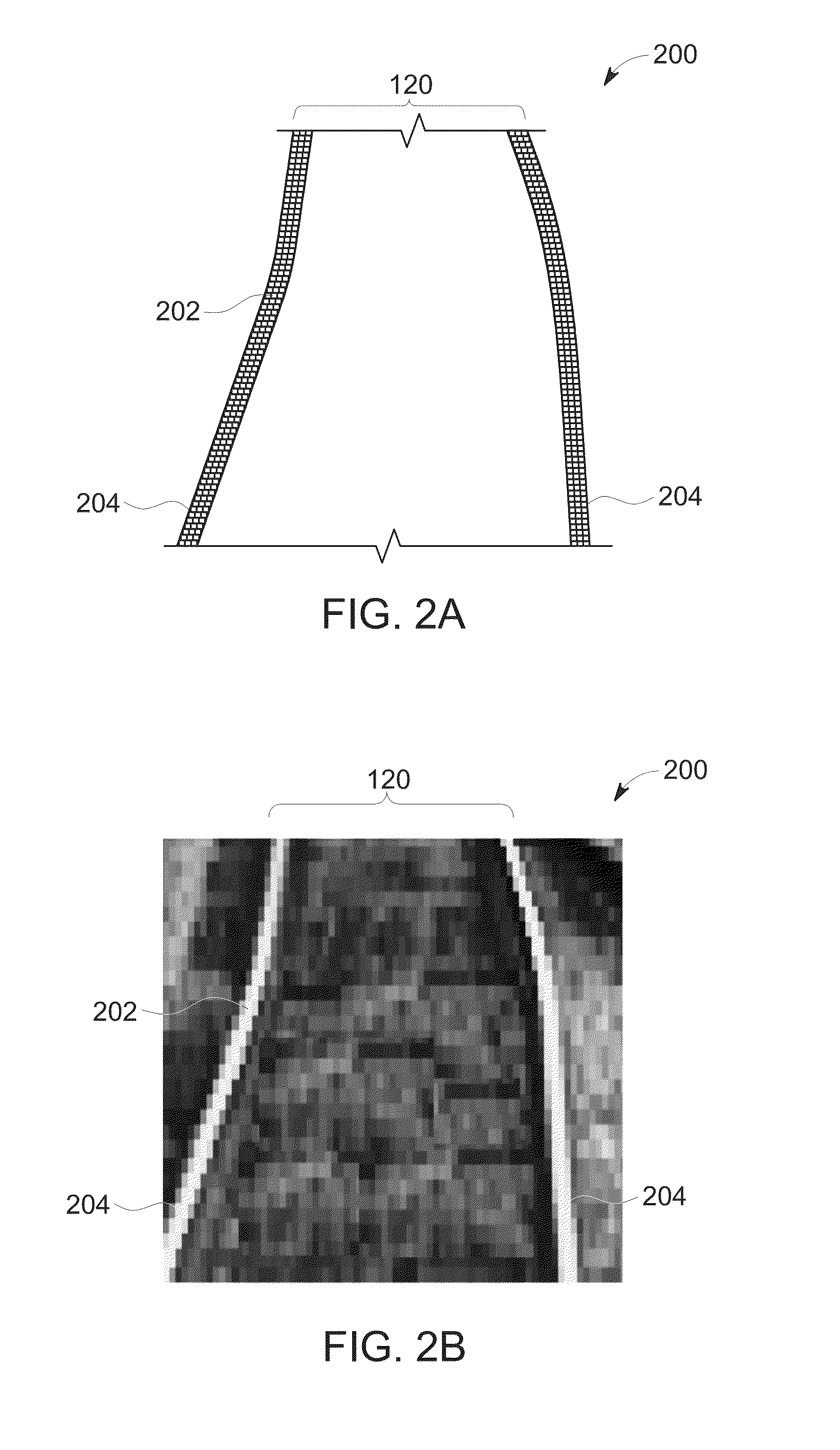
[0021]One or more examples of the inventive subject matter described herein include systems and methods for detecting misalignment of track traveled by rail vehicles. The systems and methods can use analysis of images of the track that are collected from a camera on the rail vehicle to detect this misalignment. Based on the detected misalignment, an operator of the rail vehicle can be alerted so that the operator can implement one or more responsive actions, such as by slowing down and / or stopping the rail vehicle.

[0022]The images of the track can be captured from a camera mounted on a rail vehicle, such as a locomotive. The camera can be oriented toward (e.g., pointing toward) the track in the direction of motion of the rail vehicle. The camera can periodically (or otherwise) capture images of the track that are analyzed for misalignment. If the track is misaligned, the track can cause derailment of the rail vehicle. Some of the systems and methods described herein detect track mis...


PUM


Abstract

A method for optically examining a route such as a track includes obtaining one or more images of a segment of a track from a camera mounted to a rail vehicle while the rail vehicle is moving along the track and selecting a benchmark visual profile of the segment of the track. The benchmark visual profile represents a designated layout of the track. The method also can include comparing the one or more images of the segment of the track with the benchmark visual profile of the track and identifying one or more differences between the one or more images and the benchmark visual profile as a misaligned segment of the track.

Description


Claims


Application Information

Patent Timeline
Owner GE GLOBAL SOURCING LLC
Why Eureka
Try Eureka