Respirator mask

a mask and respirator technology, applied in the field of masks, can solve the problems of patient discomfort, masks that do not fit properly, and impaired patient's vision,

Inactive Publication Date: 2015-10-01
AUSTRALIAN CENT FOR ADVANCED MEDICAL TECH
View PDF2 Cites 16 Cited by
  • Summary
  • Abstract
  • Description
  • Claims
  • Application Information

AI Technical Summary

Benefits of technology

[0014]In abroad aspect, the present invention provides a mask which has a flexible manifold and face-contacting components which can be distorted into different shapes to suit differing facial contours when applying tensile forces to the mask, typically by means of a straps and a harness. The nature of the connection between the straps and the mask is such that loadings applied to the mask via the straps are distributed so that distortions of the mask under load will not compromise the required air seal between the users face and the face contacting part of the mask.

Problems solved by technology

In some cases, patients find them uncomfortable.
In particular, the relatively thicker sections of the face contacting part can cause discomfort when pressed against a patient's face at the pressures required to create a gas tight seal.
This is a particular problem where high therapeutic gas pressures are required.
In other cases, such masks do not fit properly, for example where the mask is too narrow in the X-Y plane for the patient's nose.
Often, the bulky rigid manifold and relatively high attachment points of the harness cause a patient's line of vision to be impaired and this can cause a degree of claustrophobia in some patients.
An additional problem arises from the use of rigid materials in mask construction, particularly for the manifold.
When a patient wearing a mask having a rigid manifold turns in bed and contacts an object such as a pillow, reaction forces from the pillow tend to push the manifold laterally and lift the face contacting part from the patient's face thereby breaking the gas tight seal and causing an air leak which prevents optimum therapy being delivered to the patient.
Hard plastic components may also cause pain or discomfort if they are pushed hard against a patient's skin during sleep.
The use of hard components also makes it difficult for a patient to sleep on their stomach, because pressure on the manifold tends to result in air leakage or patient discomfort.
Such masks can be difficult for some patients to dismantle and clean.
In addition parts can become broken or lost.
A mask made from many parts is typically more expensive to produce than a mask having fewer parts, due to increased moulding costs for the many different parts, and assembly and inventory costs.
A further problem with existing conventional masks is that a substantial number of patients leak gas from their mouth during positive gas pressure therapy.
However one of the problems with these masks for some patients is that they do not succeed in fully preventing gas leakage from the patient's mouth.
Often gas leakage is preceded by stretching and ballooning of the patient's cheeks, which tends to substantially change the facial contours adjacent the face sealing portion of the masks.
This significant facial deformation has the effect of breaking the gas tight seal around the mask, since the face contacting portion of the mask presents a relatively rigid sealing surface incapable of adapting to such large changes in facial contours.

Method used


Image

  • Respirator mask
  • Respirator mask
  • Respirator mask

Examples


Embodiment Construction

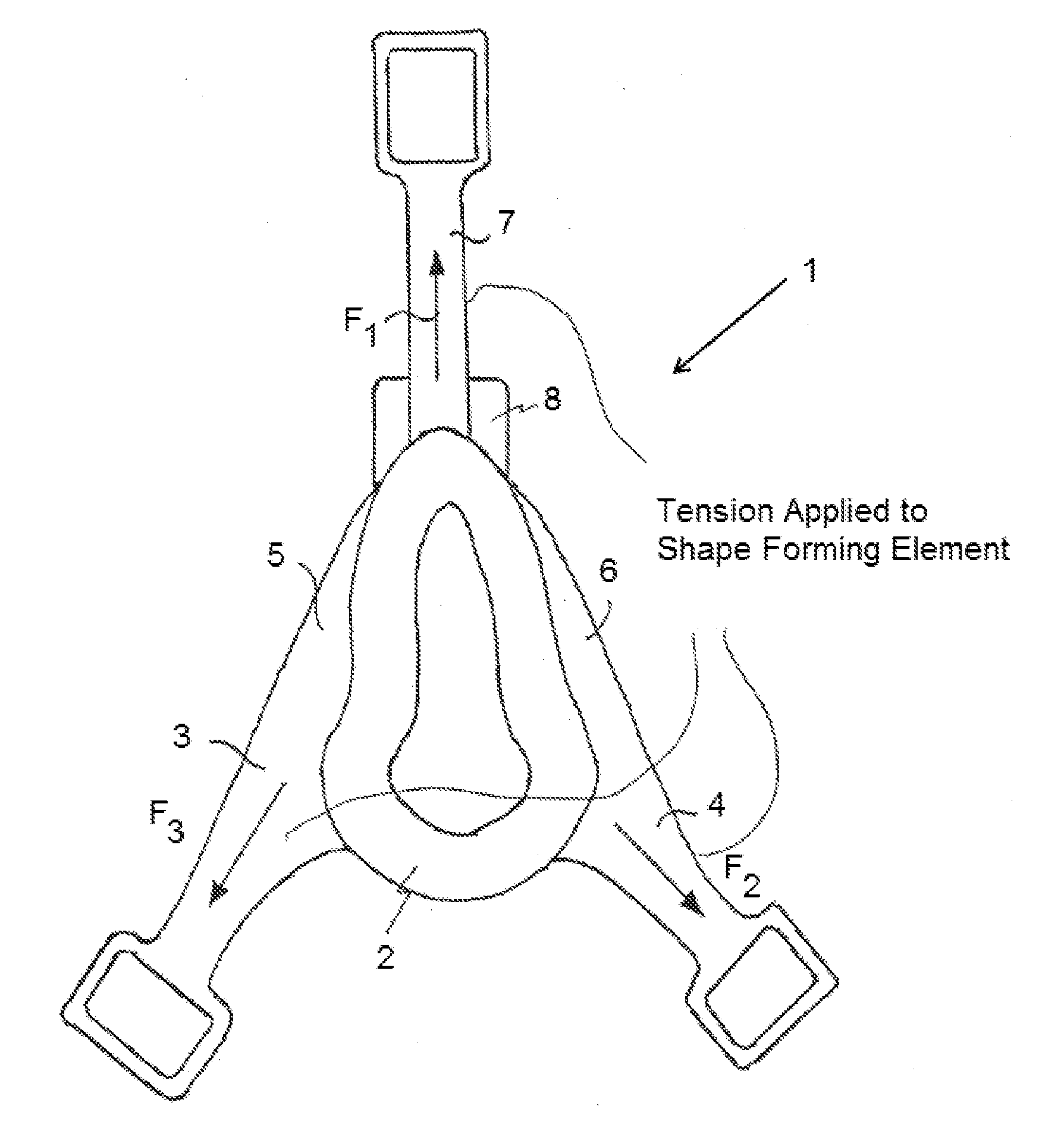
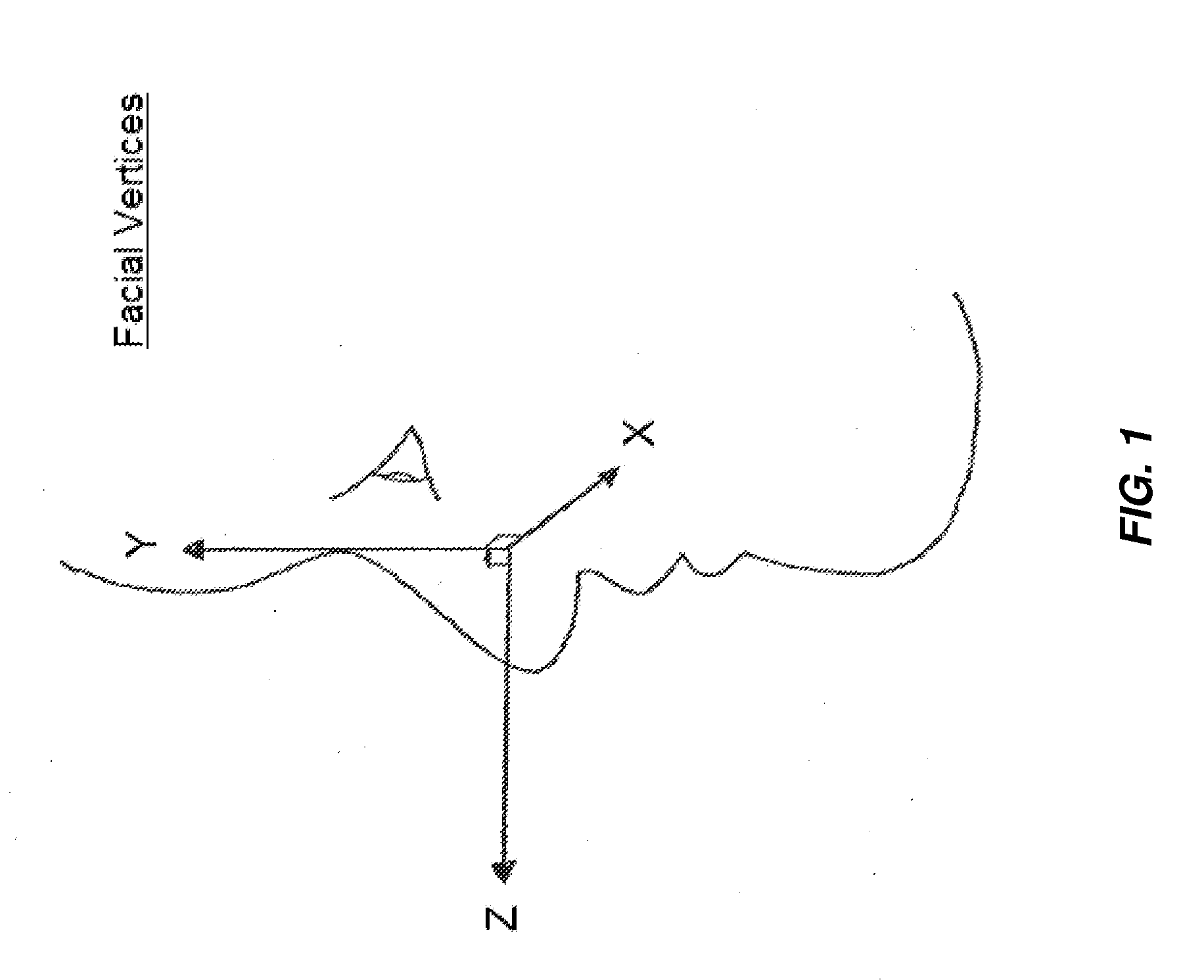
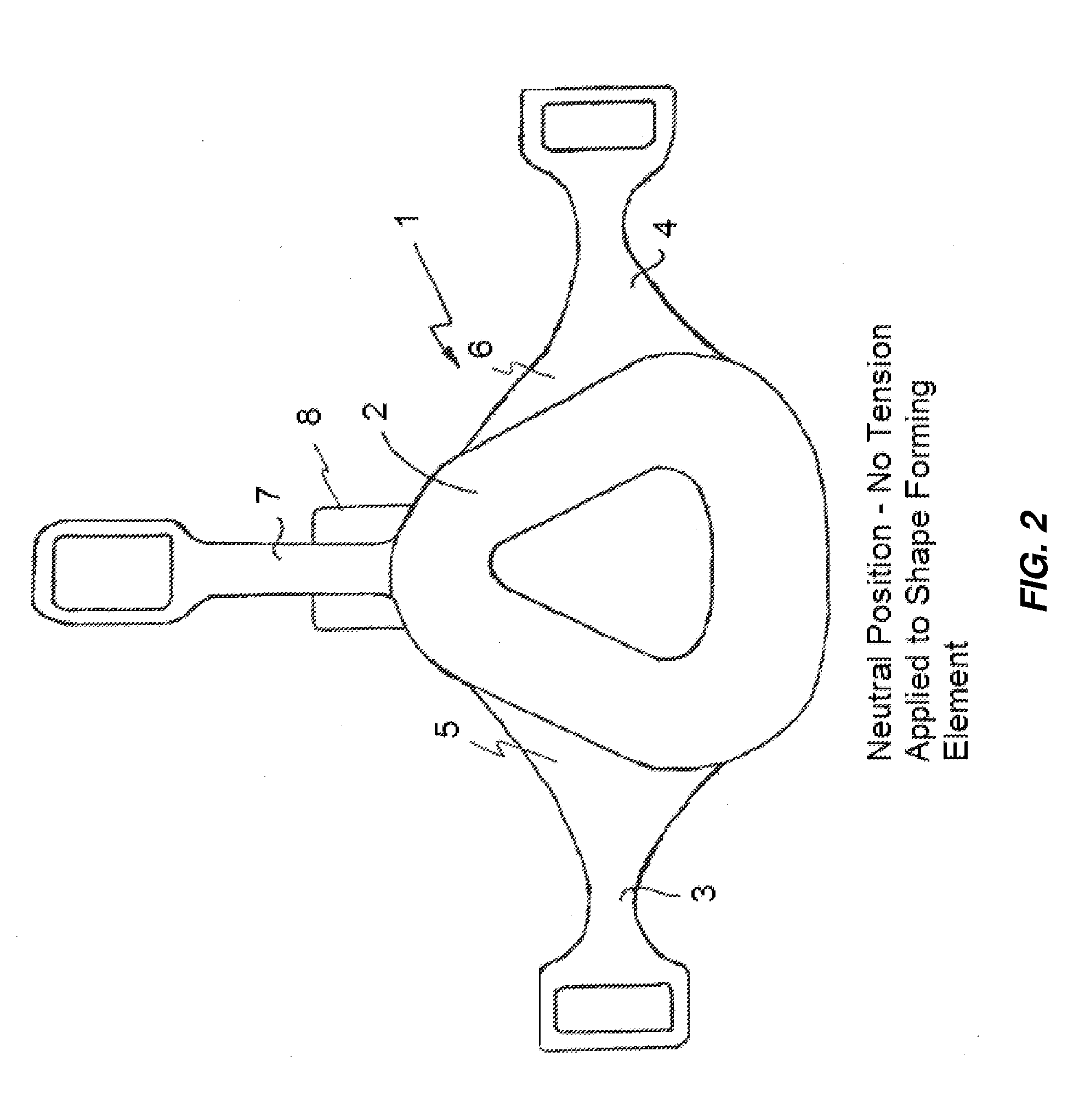
[0152]Referring to the drawings, FIG. 1 shows a schematic view of a face indicating the X, Y and Z axes. FIGS. 2 to 10 schematically illustrate a first embodiment of a mask 1 and the principles governing the design and operation of that mask in response to the use of an enlarged web contact portion. FIG. 2 shows a back side elevation of the mask 1. Mask 1 includes a flexible face contacting element 2 and straps 3 and 4. Each of straps 3 and 4 respectively include enlarged web portions 5 and 6 which transfer loads from the straps to the manifold. Mask 1 has been moulded in a single piece from a flexible elastomeric material, most preferably a medical grade silicone. However, any suitable elastomeric material may be used. Mask 1 further includes a third strap 7 and an air inlet 8. The mask of FIG. 1 is shown in a configuration without applied loads. FIG. 3 shows the mask 1 of FIG. 1 with corresponding numbering. The mask in FIG. 3 is shown with straps under a load creating a distortio...


PUM


Abstract

A mask for supplying gas under pressure to an airway of a human including a flexible manifold shell, an air inlet connected to an air delivery pipe, and at least two side walls which are at least partially formed by portions of the manifold shell. A flexible face contacting element defines an orifice to accommodate the nose of the human. Straps connected to the mask allow forces exerted by the straps to deform the manifold shell at least along X and Y axes, creating a variety of different orifice shapes. The face contacting part includes a flexible membrane allowing X and Y axis movement of the mask and movement of the mask along a Z axis between the user's face and the manifold shell. The flexible membrane may deform while retaining a gas seal against the face of a wearer.

Description

CROSS-REFERENCE TO RELATED APPLICATIONS[0001]This application is a Continuation of U.S. patent application Ser. No. 12 / 443,415 entitled “IMPROVED RESPIRATOR MASK,” filed on Oct. 29, 2009, which is a U.S. national stage application under and claims the benefit of 35 U.S.C. §371 of International Application No. PCT / AU2007 / 001455, filed on Sep. 28, 2007, entitled “IMPROVED RESPIRATOR MASK,” which claims priority to Australian application no. 2006905360, filed on Sep. 28, 2006, entitled “IMPROVED RESPIRATOR MASK” each of which are incorporated herein by reference in their entireties.FIELD OF THE INVENTION[0002]This invention relates to a mask, in particular to a mask for supplying gases, typically air or oxygen, to the airways (nose or no and mouth) of humans. Such masks are often referred to as “respirator masks”. Such masks are particularly suited to applying continuous positive airway pressure (CPA) to patients for treatment of sleep apnea, however the invention is not in any way lim...

Claims


Application Information

Patent Timeline
Patent Type & Authority Applications(United States)
IPC IPC(8): A61M16/06
CPCA61M16/0616A61M16/0683A61M16/06A61M16/0633A61M16/0057
Inventor SULLIVAN, COLINSPENCER, PETER
Owner AUSTRALIAN CENT FOR ADVANCED MEDICAL TECH
Why Eureka
Try Eureka