Cap with a bill having upper and lower portions displaying information when spaced-apart

a technology of bill and upper portion, applied in the field of improving headgear, can solve problems such as plastic integration

Active Publication Date: 2015-11-19
CISCO SALES
View PDF14 Cites 12 Cited by
  • Summary
  • Abstract
  • Description
  • Claims
  • Application Information

AI Technical Summary

Benefits of technology

[0020](c) Directly integrating a specifically printed augmented reality marker within the artwork on the upper and lower bill members, the marker allowing it to be scanned by smart devices (phone, tablet, etc.) providing an interactive experience while viewing from a smart device based on the specific software that has been developed for this individual marker.
[0021](d) Installing a lenticular lens over th

Problems solved by technology

(1) Use of a pressure point hinge system where upper bill and lower bill are completely separate entities; the upper bill is cut with precision in regards to location and size, thus creating a functionally sound hinge mechanism with maximum surface area for artwork. When the hinge mechanism is in place, a cut out portion of the top visor creates two lengthened legs that produce pressure on the outer most points of the lower visor; the pressure creating a natural curve of the lower bill portion. The ability to curve the bottom bill while the top bill member is upright allows improved protection from the sun versus bottom bills that are straight, or horizontal. Other headgear of similar nature have their lower bill remain flat when flipped open, while the lower bill of the present invention preserves a natural curve synonymous with the comfort and style of a classic baseball cap.
(2) Using oval designed female snap closure openings on the upper bill in conjunction with a specific tolerance in regards to thickness of upper and lower bills allowing the bottom male pins to move naturally side to side when the cap bill is curved or ben

Method used


Image

  • Cap with a bill having upper and lower portions displaying information when spaced-apart
  • Cap with a bill having upper and lower portions displaying information when spaced-apart
  • Cap with a bill having upper and lower portions displaying information when spaced-apart

Examples


Embodiment Construction

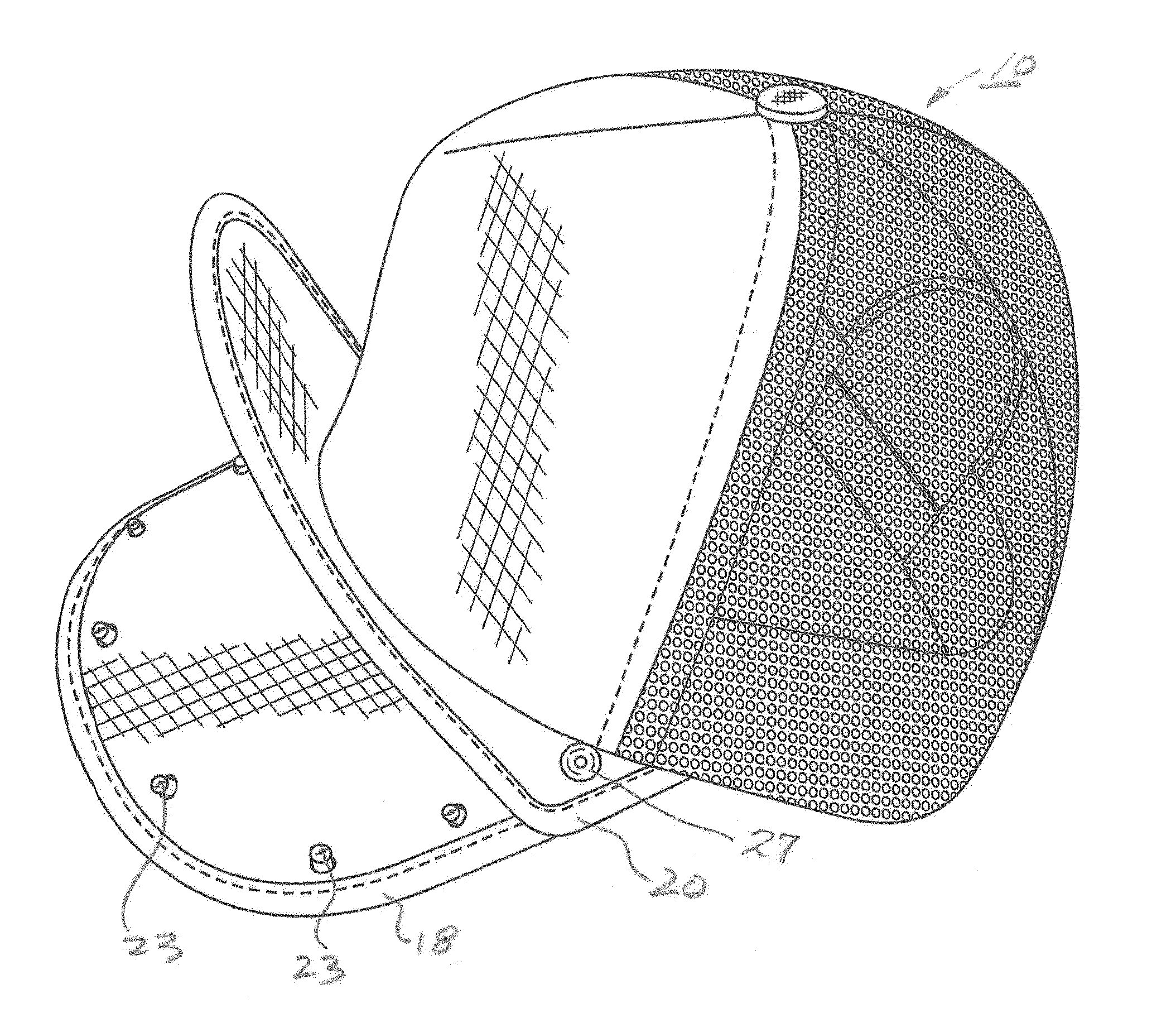
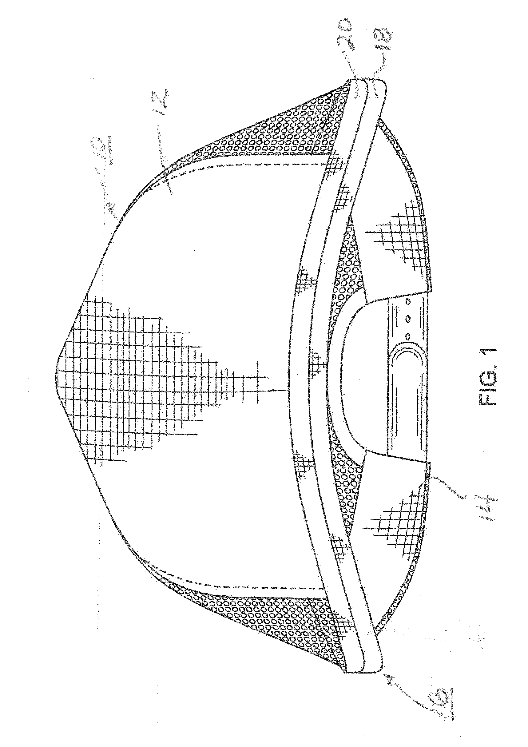
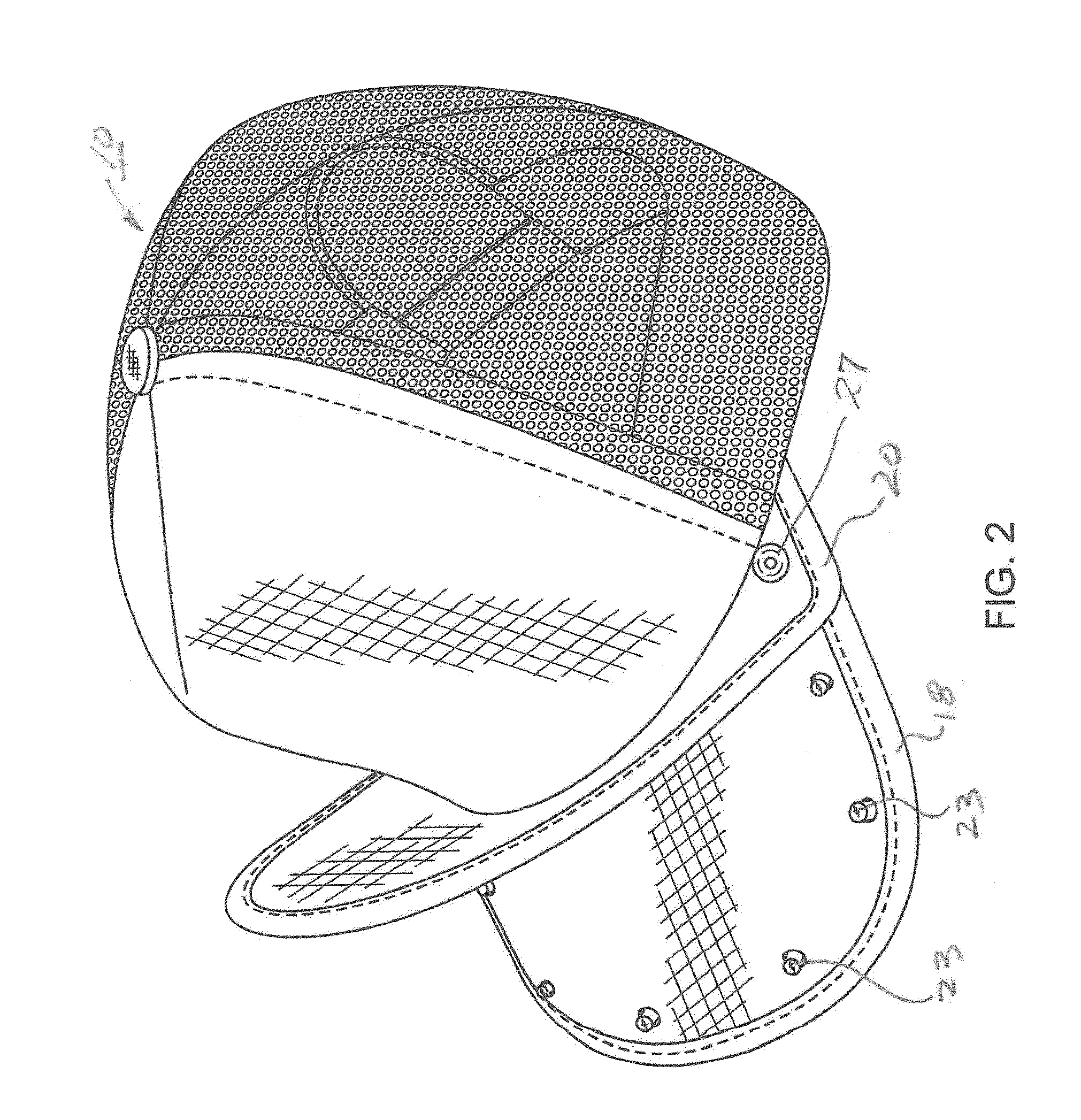
[0048]FIG. 1 is a front view of a flip cap 10 incorporating the teachings of the present invention (note that the present invention can be used as a flip visor). Cap 10 includes a crown portion 12 to be worn on the head of a wearer and a headband 14. Bill portion 16 comprises lower member 18 and upper member 20, upper member 20 being pivotally connected to lower member 18. Upper member 20 is removably secured to lower member 18, a plurality of oval shaped openings, or holes, 22 (FIG. 3), formed thereon engaging upright male pins 23 secured to lower member 18 when the upper and lower members are pushed together by the wearer. Rivets 27 (see FIG. 4) formed on upper bill member 20 go through aligned openings 31, and 41 in lower bill portion 18 secure both bill pivoting securely. When it is desired to display a message placed on the surface of a plastic board 19 sewn to upper member 20 as shown in FIG. 3, upper member 20 is separated from lower member 18 by the wearer and moved upwardly...


PUM


Abstract

A flip cap which has crown and bill portions, the bill having upper and lower members, at least one of the upper and lower members having a surface capable of displaying information secured thereto when the upper and lower members are spaced-apart.

Description

RELATED APPLICATIONS[0001]This application is a continuation-in-part application of application Ser. No. 13 / 894,584, filed on May 15, 2013.BACKGROUND OF THE INVENTION[0002]1. Field of the Invention[0003]This invention relates to improving headgear that is comprised of a visor that flips open and closed, the visor having a fixed lower portion and a movable upper portion. Both bill portions have the capability of visually displaying information to a person near the wearer.[0004]2. Description of the Prior Art[0005]Various types of caps having a bill that can move from a first to second position for entertainment and advertising purposes have been available in the prior art.[0006]For example, U.S. Pat. No. 4,777,667 to Patterson et al discloses a flip bill cap wherein the bill portion is adapted to be raised to disclose an entertaining and advertising message thereon. The bill portion is activated by the cap wearer using either a string or a solenoid. Indicia is formed directly on the ...

Claims


Application Information

Patent Timeline
IPC IPC(8): A42B1/06A42B1/00A42B1/24
CPCA42B1/064A42B1/245A42B1/004A42B1/242A42B1/248A42B1/0184G09F21/02G09F21/023
Inventor KAY, JORDAN S.KAY, NEIL J.
Owner CISCO SALES
Why Eureka
Try Eureka