Multi-point switching apparatus

a switching apparatus and multi-point technology, applied in the direction of fixed resistors with intervening connectors, resistors with sliding contacts, contacts, etc., can solve the problems of unlikely electrical connection, likely electric connection, and short circui

Inactive Publication Date: 2015-11-19
ALPS ALPINE CO LTD
View PDF7 Cites 2 Cited by
  • Summary
  • Abstract
  • Description
  • Claims
  • Application Information

AI Technical Summary

Problems solved by technology

However, the switching device 100 has been problematic in that when a switchover is made from one to-be-switched pattern 123 to its adjacent to-be-switched pattern 123, the slider 124 is not likely to be electrically connected to either to-be-switched pattern 123.
Another problem has been that an electric connection is likely to be made to the two to-be-switched patter

Method used


Image

  • Multi-point switching apparatus
  • Multi-point switching apparatus
  • Multi-point switching apparatus

Examples


first embodiment

[0023]An embodiment of the present invention will be described below in detail with reference to the drawings. For easy comprehension, dimensions on the drawings have been appropriately changed.

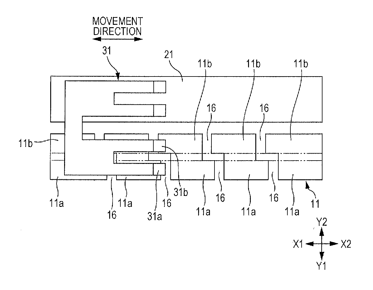
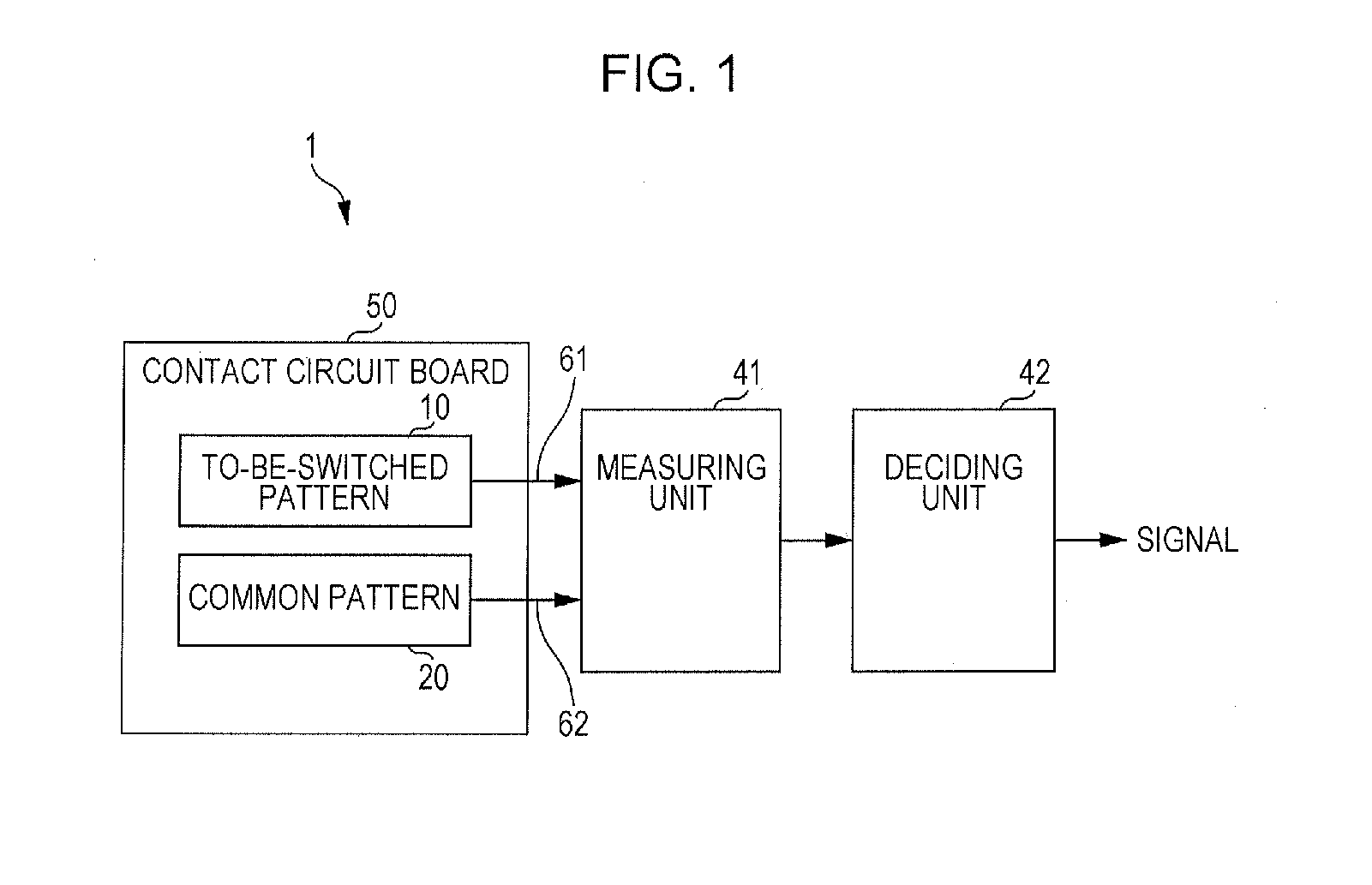
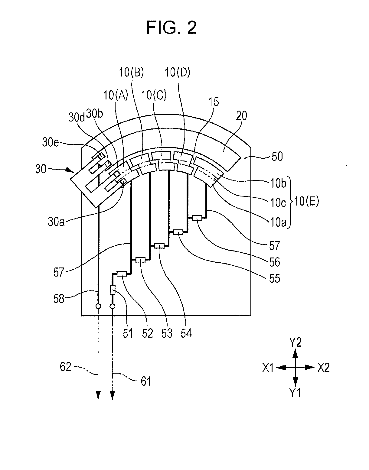
[0024]FIG. 1 is a block diagram of a multi-point switching apparatus 1 in an embodiment of the present invention. FIG. 2 schematically illustrates a contact circuit board 50 and a slider 30. FIG. 3 schematically illustrates to-be-switched patterns. FIG. 4A is a plan view of the slider 30 and FIG. 4B is its front view, illustrating the outer shape of the slider 30. FIG. 5 schematically illustrates an example of a position to which the slider 30 is moved. FIG. 6 is a graph indicating values measured by a measuring unit;

[0025]The multi-point switching apparatus 1 in this embodiment includes the contact circuit board 50, a measuring unit 41 connected to a to-be-switched pattern 10 and a common pattern 20, which are placed on the contact circuit board 50, and a deciding unit 42 connected to the me...


PUM


Abstract

A multi-point switching apparatus includes a continuous common pattern formed on a contact circuit board, equally spaced to-be-switched patterns, and a slider that is brought into sliding contact with both the common pattern and one to-be-switched pattern. The slider is moved to make a switchover in succession. The slider includes a first sliding part and second sliding part that are elastically deformable individually. Each to-be-switched pattern includes a first pattern part placed so as to be brought into sliding contact with the first sliding part and a second pattern part placed so as to be brought into sliding contact with the second sliding part. The first pattern part and second pattern part are electrically connected to each other for each of the to-be-switched patterns. While any of the first sliding part and second sliding part is in a space, the other is in sliding contact with the to-be-switched pattern.

Description

CLAIM OF PRIORITY[0001]This application claims benefit of priority to Japanese Patent Application No. 2014-099723 filed on May 13, 2014, which is hereby incorporated by reference in its entirety.BACKGROUND[0002]1. Field of the Disclosure[0003]The present disclosure relates to a multi-point switching apparatus that enables a stable switching operation while maintaining a continuous electric connection.[0004]2. Description of the Related Art[0005]Multi-point switching apparatuses in which a slider is electrically connected to one of a plurality of patterns to be switched in a selective manner are used in various fields. A multi-point input switching device suitable for input signal switching is disclosed in, for example, Japanese Unexamined Patent Application Publication No. 55-95215.[0006]FIG. 9 illustrates the principle of a switching device 100 described in Japanese Unexamined Patent Application Publication No. 55-95215 as a conventional switching device. FIG. 10 illustrates the pr...

Claims


Application Information

Patent Timeline
IPC IPC(8): H01H15/00H01H15/10
CPCH01H15/10H01H15/005H01H19/10H01H19/14H01H19/585H01C10/36H01C10/48H01H1/365H01H1/44
Inventor KIKUCHI, TSUYOSHI
Owner ALPS ALPINE CO LTD
Why Eureka
Try Eureka