Tape Measure Anchor

Active Publication Date: 2015-12-03
RYAN HENRY S
View PDF9 Cites 2 Cited by
  • Summary
  • Abstract
  • Description
  • Claims
  • Application Information

AI Technical Summary

Benefits of technology

[0006]The primary advantage of the present invention is not only that it is adapted for use with a number of different tape measures, but more specifically the weights, which are composed of a magnetic material. In this way, the weights are magnetically coupled to each other and to the elevator bolt. This prevents the weights from shifting or moving extensively during use, providing additional stability to the end of the tape measure.
[0007]Devices have been disclosed in the prior art that relate to attachments for tape measures. These include devices that have been patented and published in patent application publications. Some of these devices disclose a holder that attaches to an end of a tape measure for stabilizing the tape measure when measuring an area on the floor. Other devices disclose an adhesive pad that attaches to an end of a tape measure for making measurements. These devices, however, do not disclose a weight anchor for a tape measure comprising a body in which one or more magnetic weights can be positioned, such that the weight of the anchor is adjustable. The foregoing is a list of devices deemed most relevant to the present disclosure, which are herein described for the purposes of highlighting and differentiating the unique aspects of the present invention, and further highlighting the drawbacks existing in the prior art.
[0008]Specifically, U.S. Pat. No. 6,295,739 to Kraft discloses a measuring tape holding device that comprises a rectangular holder body having a slot thereon. The slot is adapted to receive a tape end tab. Thereafter, the holder body and the tape end tab can be nailed to a surface such as the floor so that the holder body and the tape end tab are fixed in place. In contrast, the present invention comprises a tape measure anchor that can be removably attached to a tape end tab. The tape measure anchor adds weig

Problems solved by technology

These devices, however, do not disclose a weight anchor for a tape measure comprising a body in which one or more magnetic weights can be positioned, such that the weight of the anchor is adjustable.
Accordingly, LeBon does not disclose an anchor having removable weights therein.
T

Method used


Image

  • Tape Measure Anchor
  • Tape Measure Anchor
  • Tape Measure Anchor

Examples


Embodiment Construction

[0025]References are made herein to the attached drawings. Like reference numerals are used throughout the drawings to depict like or similar elements of the tape measure anchor. For the purposes of presenting a brief and clear description of the present invention, the preferred embodiment will be discussed as used to maintain an end of a tape measure in place and prevent the tape measure from swinging. The figures are intended for representative purposes only and should not be considered to be limiting in any respect.

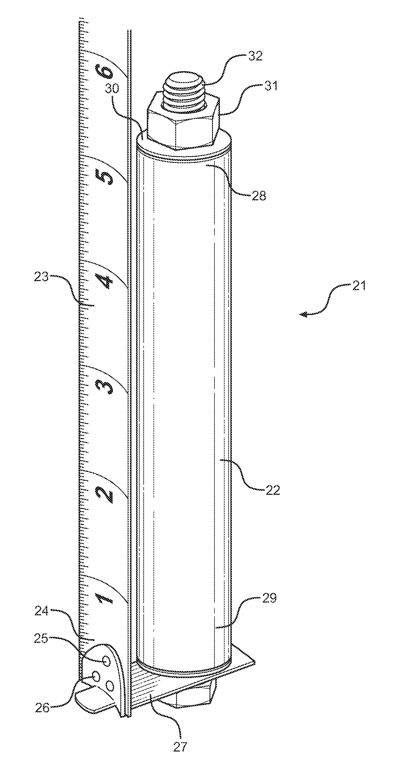
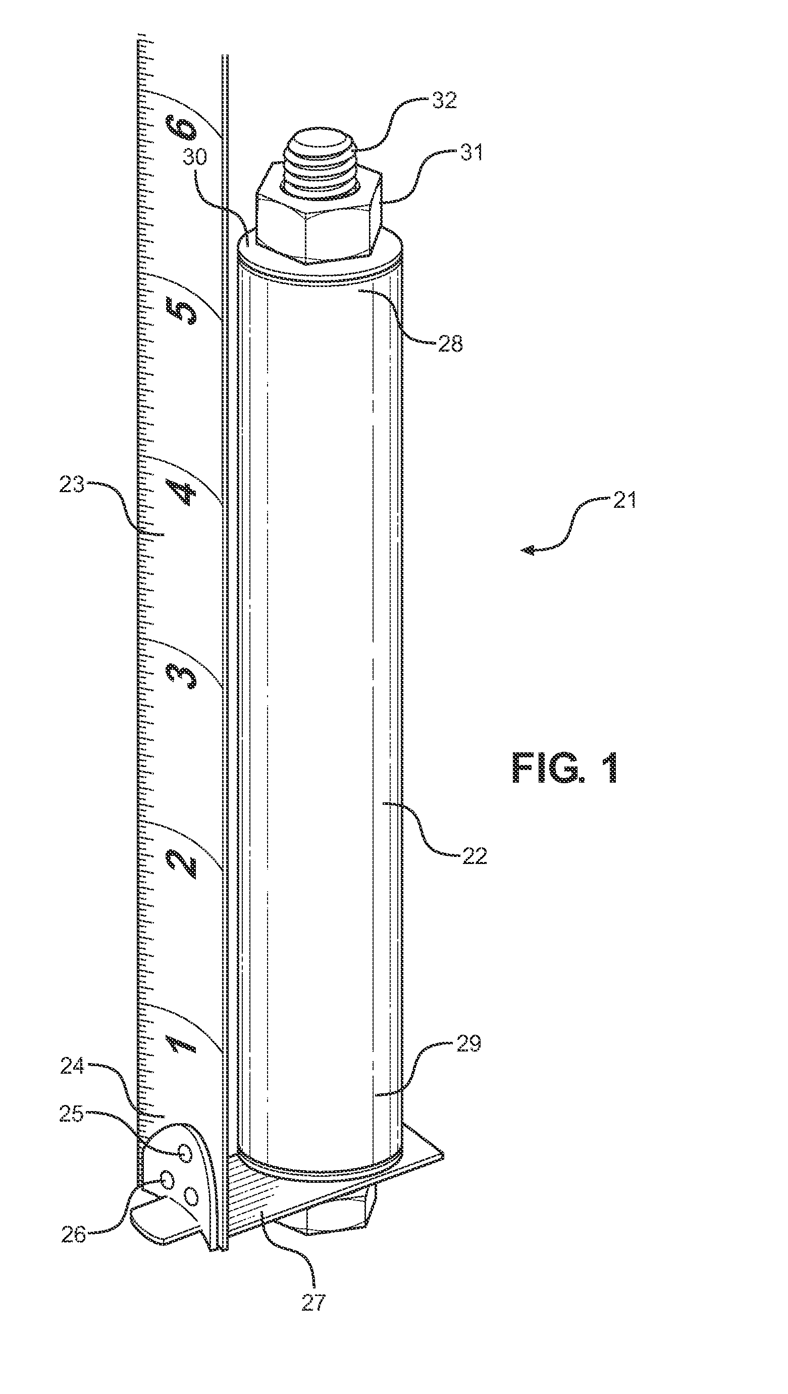
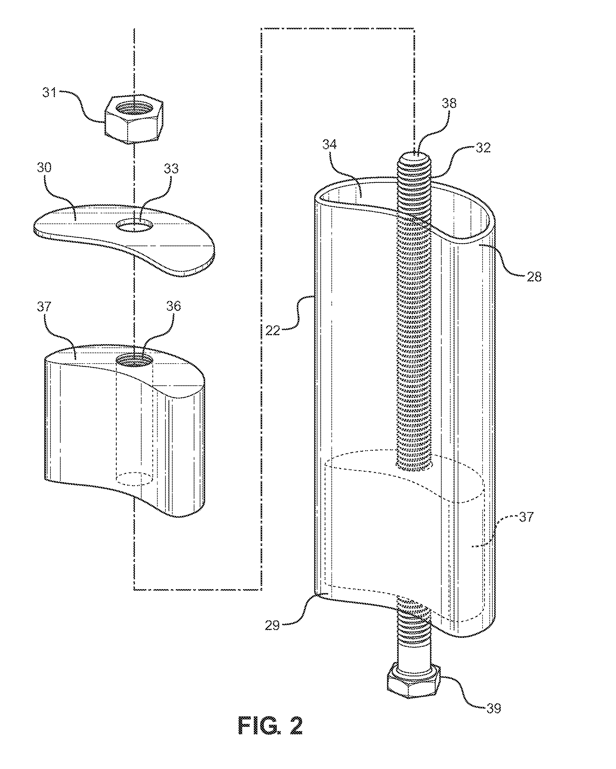
[0026]Referring now to FIG. 1, there is shown a perspective view of the present invention as installed on a tape measure 23. The tape measure anchor 21 of the present invention comprises a substantially tubular housing 22 having an open upper end 28 and a closed lower end 29. The housing 22 comprises a defined interior volume for storing one or more weights therein. The lower end 29 comprises an elevator bolt 32 that extends vertically upward therefrom and towards the ...


PUM


Abstract

Provided is a weighted anchor for a tape measure. The device includes a tubular housing with a defined interior volume for holding one or more magnetic weights therein. The weights are positioned around an elevator bolt disposed within the interior volume, then secured within the interior volume via a washer and a bolt. In this way, the weights are arranged in a stacked orientation. The housing can be secured to an end of a standard tape measure, thereby weighing down the same. In this way, the present invention can prevent the tape measure from swinging or otherwise oscillating when measuring long distances.

Description

CROSS REFERENCE TO RELATED APPLICATION[0001]This application claims the benefit of U.S. Provisional Application No. 62 / 003,782 filed on May 28, 2014. The above identified patent application is herein incorporated by reference in its entirety to provide continuity of disclosure.BACKGROUND OF THE INVENTIONField of the Invention[0002]The present invention relates to an attachment for tape measures. More specifically, the present invention pertains to an improved weighted anchor for tape measures. In one embodiment, the present invention comprises a housing with one or more magnetic weights enclosed therein. The magnetic weights are removable, so that the present invention is readily adjustable in weight.[0003]A tape measure is a common measuring tool comprising a flexible ruler. Its design allows for a measure of great length to be easily carried in pocket or toolbox and permits individuals to measure around curves and corners. Due to its flexible nature, however, tape measures can be ...

Claims


Application Information

Patent Timeline
IPC IPC(8): G01B3/10
CPCG01B3/1071G01B2003/1076
Inventor RYAN, HENRY S.
Owner RYAN HENRY S
Why Eureka
Try Eureka