Computation device, computation method, and medium

a computation device and computation method technology, applied in the field of computation devices, can solve the problems of wasting time equivalent to the time equivalent to this timing difference, and it is difficult for the array processor b>19/b> to appropriately execute an operation in some cases, so as to suppress the increase in circuit scale and power consumption, and improve operation efficiency

Active Publication Date: 2015-12-03
NEC CORP
View PDF4 Cites 4 Cited by
  • Summary
  • Abstract
  • Description
  • Claims
  • Application Information

AI Technical Summary

Benefits of technology

[0024]According to the present invention, it is possible to enhance operation efficiency while suppressing increase in circuit scale and in power consumption.

Problems solved by technology

Therefore, when timings of data input after reaching the operation processing unit 15 are different, it is difficult for the array processor 19 to appropriately execute an operation in some cases.
A time equivalent to this timing difference becomes a wasted time.

Method used


Image

  • Computation device, computation method, and medium
  • Computation device, computation method, and medium
  • Computation device, computation method, and medium

Examples


first exemplary embodiment

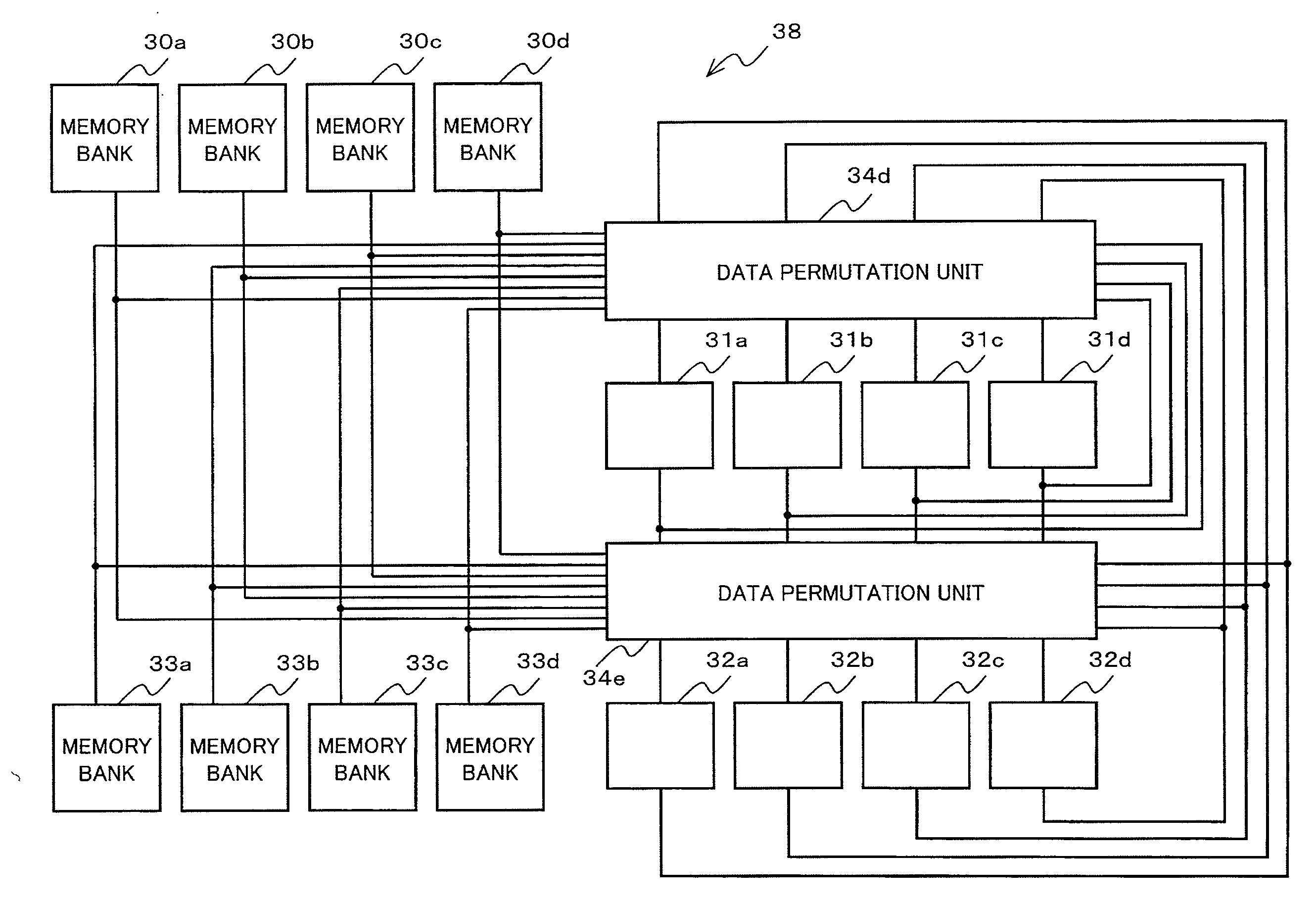
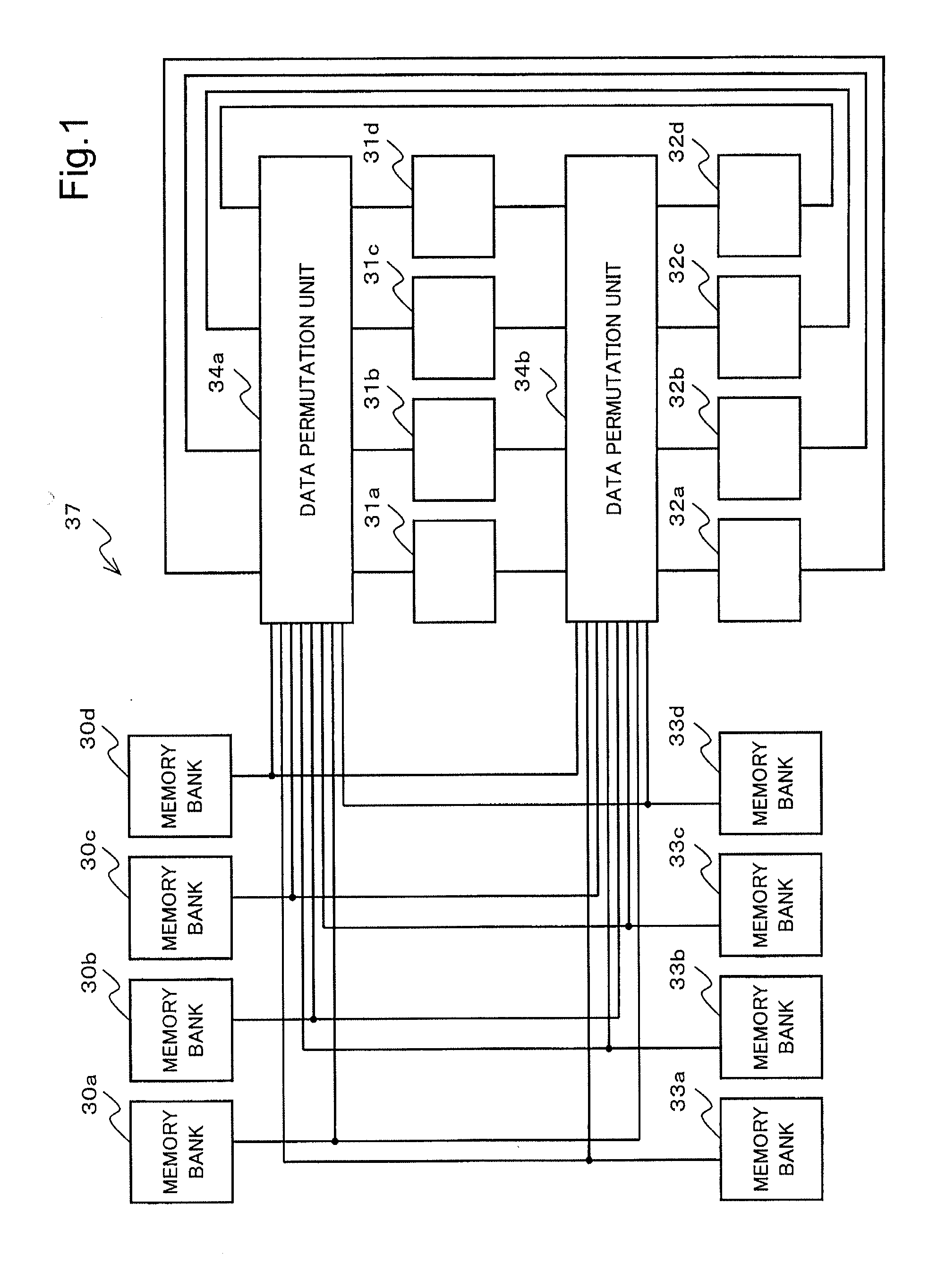
[0035]FIG. 1 is a block diagram illustrating an example of a configuration of a computation device 37 according to a first exemplary embodiment of the present invention.

[0036]The computation device 37 includes memory banks 30a to 30d, memory banks 33a to 33d, operation processing units 31a to 31d, operation processing units 32a to 32d, and data permutation units 34a to 34b. Hereinafter, the memory banks 30a to 30d will be collectively referred to as a memory bank 30. In the same manner, the memory banks 33a to 33d will be collectively referred to as a memory bank 33. The operation processing units 31a to 31d will be collectively referred to as an operation processing unit 31. The operation processing units 32a to 32d will be collectively referred to as an operation processing unit 32. The data permutation units 34a and 34b will be collectively referred to as a data permutation unit 34.

[0037]As illustrated in FIG. 1, the computation device 37 according to the present exemplary embodi...

modified example

[0148]The configuration of the computation device 37 is not limited to the above description.

[0149]In the computation device 37, for example, at least a part of the memory bank 30, the memory bank 33, the operation processing unit 31, the operation processing unit 32, and the data permutation unit 34 may be a separate device connected via a network or a bus.

[0150]Further, in the computation device 37, each component may be divided into a plurality of components.

[0151]For example, in the data permutation unit 34, each component may be configured by using a separate device connected via a network or a bus.

[0152]Further, in the data permutation unit 34, a plurality of components may be configured as one component.

[0153]The data permutation unit 34 may be realized, for example, as a computer including a CPU (Central Processing Unit), a ROM (Read Only Memory), a RAM (Random Access Memory), and an interface circuit (IF).

[0154]FIG. 6 is a block diagram illustrating an example of a configur...

second exemplary embodiment

[0163]Next, a computation device 37 according to a second exemplary embodiment of the present invention will be described with reference to the drawings.

[0164]A configuration of the computation device 37 according to the present exemplary embodiment is the same as the computation device 37 according to the first exemplary embodiment, and therefore, description of the configuration is omitted.

[0165]The computation device 37 according to the present exemplary embodiment operates in the same manner as the first exemplary embodiment except that permutation control of the data permutation unit 34 is different. Therefore, description of the same operation is omitted and an operation specific to the present exemplary embodiment will be described.

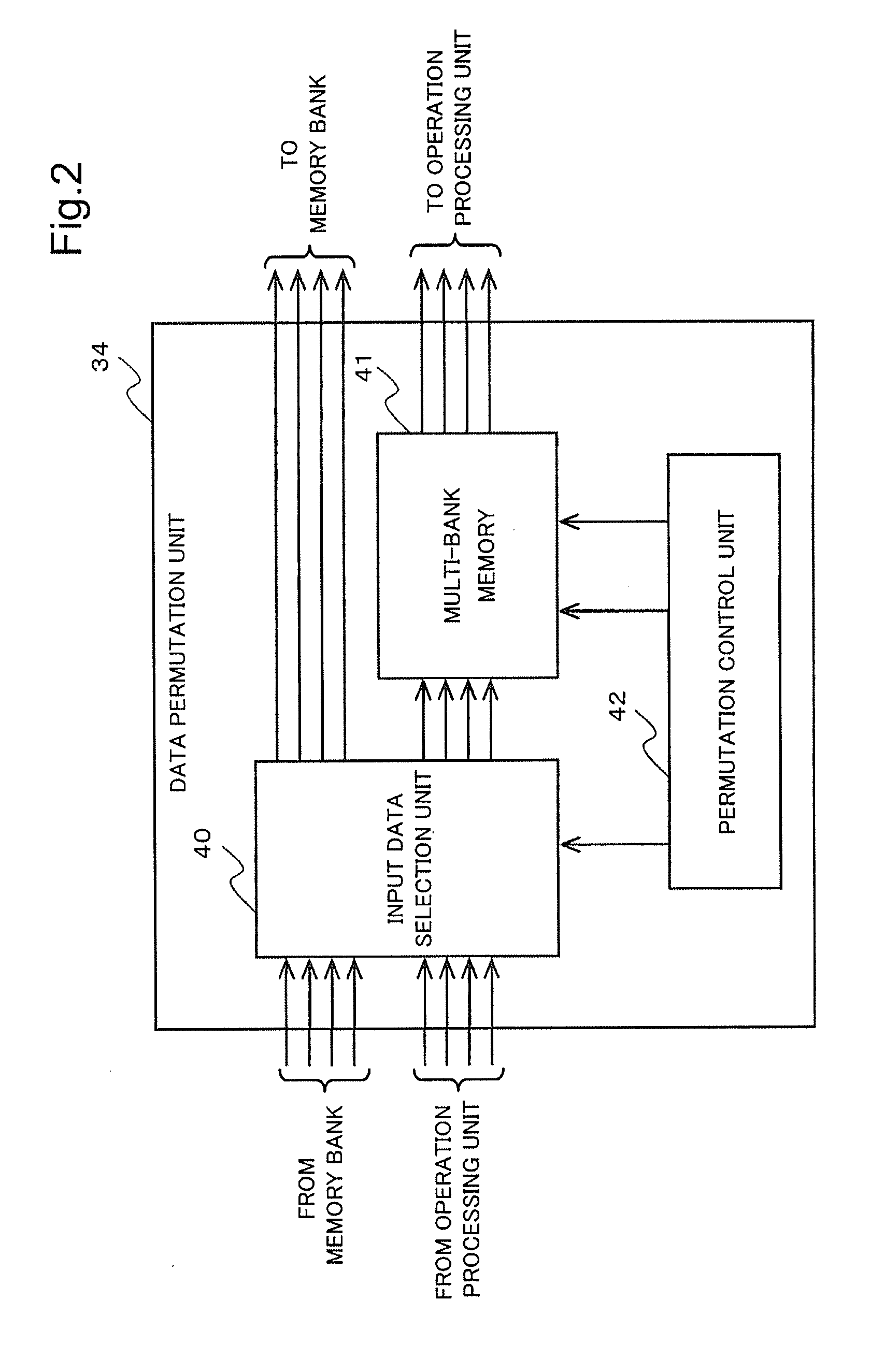
[0166]The input data selection unit 40 according to the first exemplary embodiment selects input data to an operation processing unit as the posterior stage and selects whether or not to output an operation result to a memory bank, based on a signa...


PUM


Abstract

A computation device according to the present invention includes: a first data storage unit that stores operation target data; an operation processing unit that executes an operation by using data; a data permutation unit that selects indicated data among the operation target data stored in the first data storage unit and data operated by the operation processing unit, provides predetermined delay for data received a delay indication among the indicated data based on a parameter, does not delay data not received a delay indication, executes permutation of indicated data based on a parameter, and outputs data operated in the operation processing unit and operation result data of the operation processing unit; and second data storage unit that stores the operation result data output by the data permutation unit.

Description

TECHNICAL FIELD[0001]The present invention relates to a computation device including a plurality of operation processing units (processors), and in particular, to a computation device that permutes data.BACKGROUND ART[0002]Signal processing handles a large amount of continuous data (stream data) as operation target data. In many cases, the signal processing repeatedly executes the same processing (an operation realized using a plurality of commands) for the large amount of data.[0003]As one processor architecture for efficiently processing a large amount of data, an array processor is available.[0004]FIG. 7 is a block diagram illustrating an example of a configuration of a general array processor 19.[0005]The array processor 19 illustrated in FIG. 7 includes an array operation unit 14 in which a plurality of operation processing units 11a to 11d (hereinafter, collectively referred to as an operation processing unit 11) and a plurality of operation processing units 12a to 12d (herein...

Claims


Application Information

Patent Timeline
Patent Type & Authority Applications(United States)
IPC IPC(8): G06F3/06
CPCG06F3/0647G06F3/0683G06F3/0608G06F12/00G06F12/06G06F7/76G06F15/167G06F15/80G06F9/30032G06F3/0607G06F3/067G06F3/0689G06F9/34G06F9/38
Inventor KOBORI, TOMOYOSHI
Owner NEC CORP
Why Eureka
Try Eureka