Color picture tube device having improved horizontal convergence

Inactive Publication Date: 2005-08-02
PANASONIC CORP
View PDF5 Cites 1 Cited by
  • Summary
  • Abstract
  • Description
  • Claims
  • Application Information

AI Technical Summary

Benefits of technology

[0007]The present invention aims to provide a color picture tube device that can produce convergence without increases in cost and in power consumption.
[0009]According to this construction, the quadrupole magnetic field is used to produce convergence. The quadrupole magnetic field can be generated by a coil to which a steady-state current is supplied, or by a magnet. This enables convergence to be produced with low cost and low power consumption. Here, depending on the vertical deflection of the plurality of electron beams, the effect of the horizontal component of the quadrupole magnetic field may not be able to be neglected. In such a case, the effect of the horizontal component is canceled out by the auxiliary magnetic field.

Problems solved by technology

However, due to the need for rectifying a horizontal deflection current of high frequency, such a horizontal deflection-synchronizing dynamic convergence technique has the drawbacks of increases in manufacturing cost and in power consumption.

Method used


Image

  • Color picture tube device having improved horizontal convergence
  • Color picture tube device having improved horizontal convergence
  • Color picture tube device having improved horizontal convergence

Examples


first embodiment

(Overall Construction of a Color Picture Tube Device)

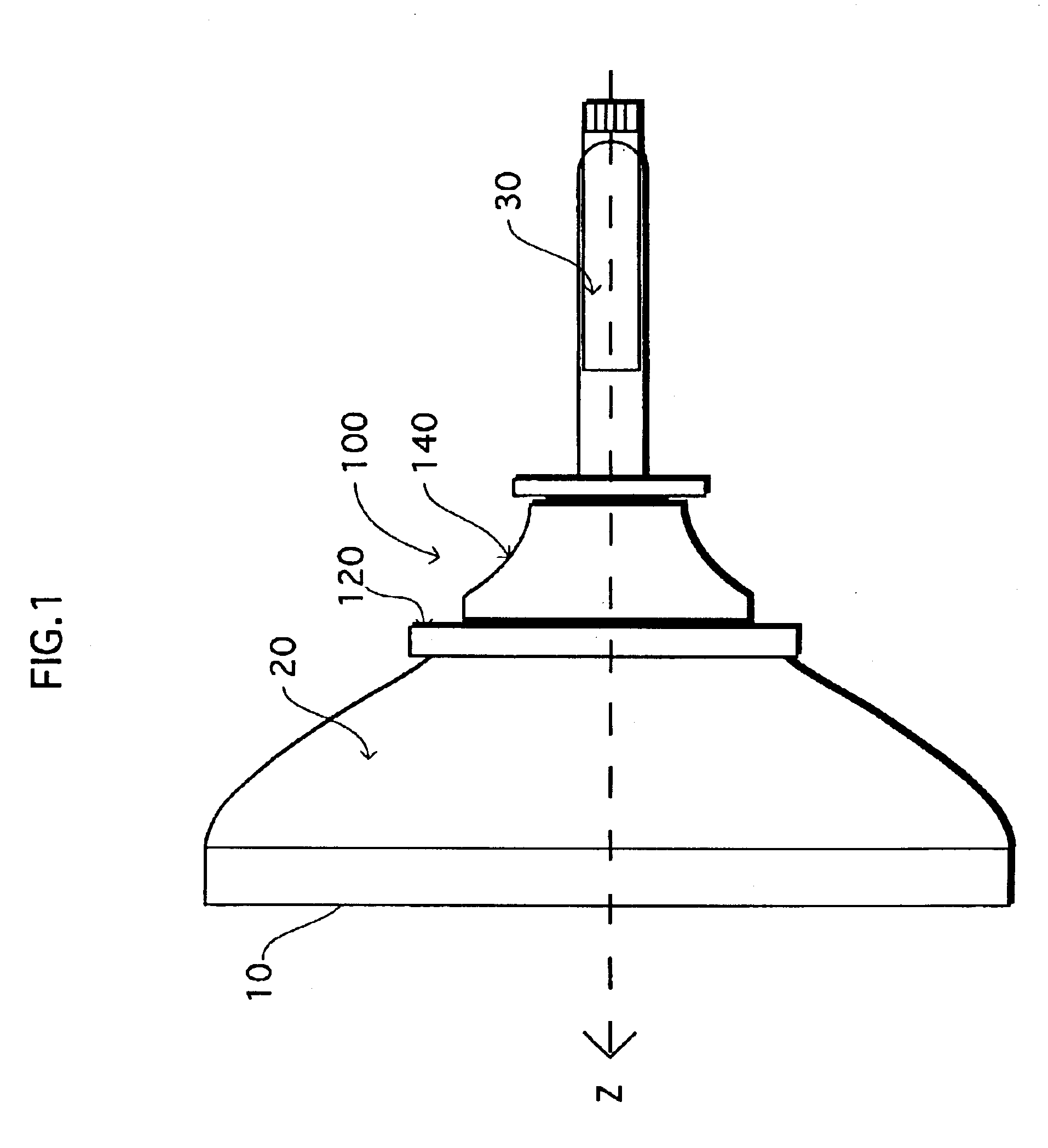
[0039]FIG. 1 is a side view of a color picture tube device to which the embodiments of the present invention relate.

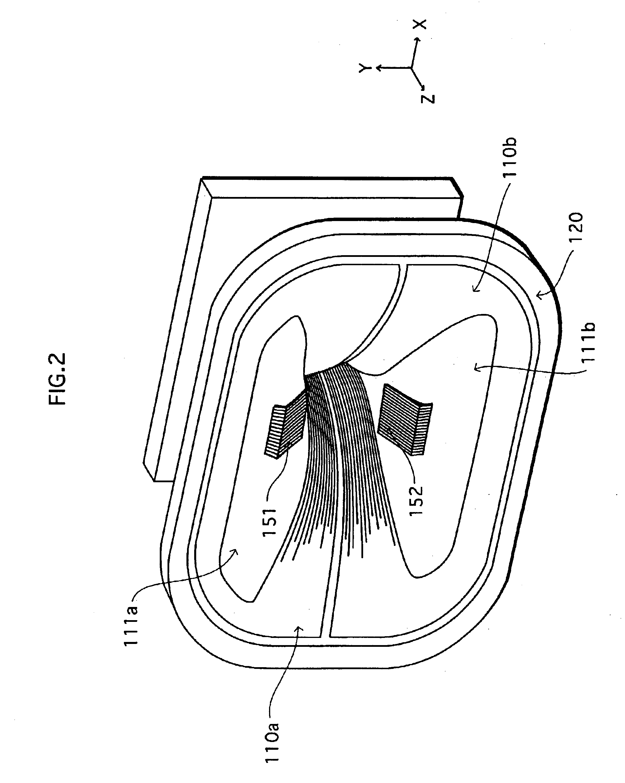
[0040]The color picture tube device is roughly made up of an envelope including a panel 10 and a funnel 20, an in-line electron gun 30, and a deflection yoke 100. A phosphor screen is formed on the internal face of the panel 10. The in-line electron gun 30 is provided in a neck of the funnel 20, and emits three electron beams toward the phosphor screen. The deflection yoke 100 is installed around the funnel 20. In the first embodiment, an electron gun that emits three horizontally-aligned electron beams in parallel with each other along the tube axis is used as the electron gun 30, so that the three electron beams are parallel with each other when entering a deflection region. The deflection region referred to here is a region where deflection magnetic fields generated by horizontal and vertical deflection coils in t...

second embodiment

[0076]The first embodiment describes how to produce convergence in a color picture tube device in which the deflection magnetic fields are substantially uniform and the three electron beams entering the deflection region are parallel with each other. In such a color picture tube device, the three electron beams will end up being underconverged in the center and edges of the phosphor screen if there is no quadrupole magnetic field. Hence the quadrupole magnetic field having the horizontal converging effect is employed to converge the three electron beams.

[0077]However, the applicable scope of the present invention is not limited to a color picture tube device in which the deflection magnetic fields are substantially uniform and the three electron beams are parallel with each other. The present invention is applicable even when the deflection magnetic fields have some distortions or when the three electron beams are not parallel with each other. In a color picture tube device that has...

third embodiment

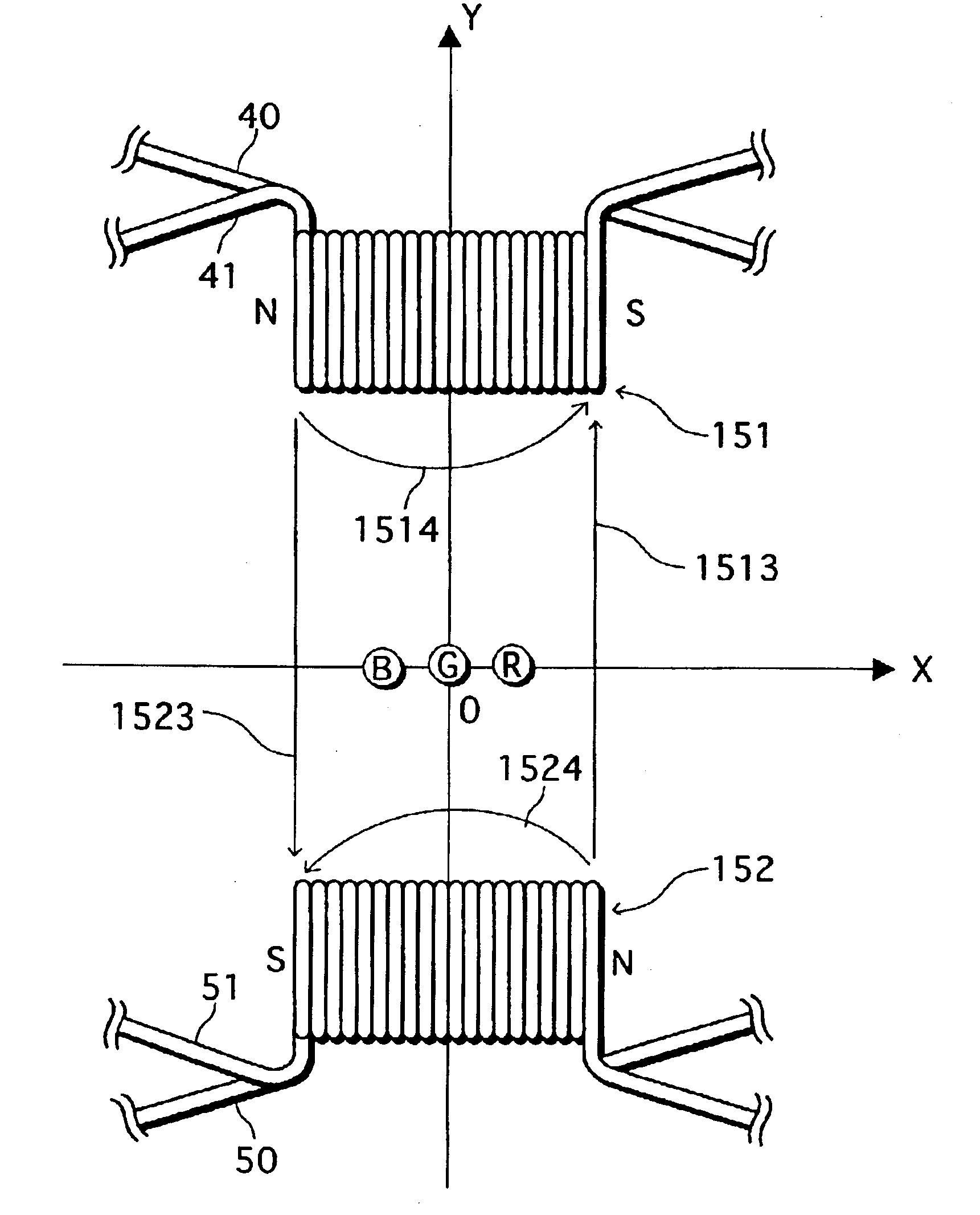
[0083]In the first and second embodiments, the auxiliary magnetic field generation wires 41 and 51 are respectively wound together with the quadrupole magnetic field generation wires 40 and 50 of the upper coil 151 and lower coil 152. The amount of current supplied to each of the auxiliary magnetic field generation wires is varied to cancel out the horizontal components of the quadrupole magnetic field in sync with the vertical deflection. In the third embodiment, the horizontal components of the quadrupole magnetic field are suppressed by varying the amount of current supplied to each of the quadrupole magnetic field generation wires themselves. This is explained in detail below.

[0084]FIG. 15 shows a construction of a quadrupole magnetic field generation coil and an effect of a quadrupole magnetic field in the third embodiment. In the drawing, the three electron beams passing between the upper coil 151 and the lower coil 152 are seen from the phosphor screen side. As illustrated, t...


PUM


Abstract

A color picture tube device that can adjust convergence without causing increases in cost and in power consumption is provided. One pair of magnetic flux generation means for generating a static quadrupole magnetic field are positioned above and below an area where a plurality of electron beams pass through. The static quadrupole magnetic field has an effect of adjusting convergence in a horizontal direction. In this construction, a magnetic flux generated by one of the two magnetic flux generation means that is closer to the plurality of electron beams is reduced, in sync with deflection of the plurality of electron beams in a vertical direction.

Description

[0001]This application is based on Japanese Patent Applications Nos. 2001-325693 and 2002-174928 with domestic priority claimed from the former application, the contents of which are hereby incorporated by reference.BACKGROUND OF THE INVENTION[0002]1. Field of the Invention[0003]The present invention relates to a color picture tube device that deflects a plurality of electron beams which are emitted from an electron gun having a plurality of in-line cathodes, and displays a color image on a phosphor screen.[0004]2. Related Art[0005]In a color picture tube device having an in-line electron gun in which cathodes corresponding to the three colors of red (R), green (G), and blue (B) are horizontally aligned, three electron beams emitted from the electron gun need to come together at an appropriate position on a phosphor screen (this is called “convergence”). Self convergence and dynamic convergence are conventional techniques which are widely used for producing convergence. Also, variou...

Claims


Application Information

Patent Timeline
IPC IPC(8): H01J29/70H01J29/51
CPCH01J29/702H01J29/705H01J2229/5681H01J2229/5682H01J2229/5687H01J29/51
Inventor TAGAMI, ETSUJISAKURAI, HIROSHINAKANO, KAZUO
Owner PANASONIC CORP
Why Eureka
Try Eureka