Computation device, computation method, and medium
a computation device and computation method technology, applied in the field of computation devices, can solve the problems of wasting time equivalent to the time equivalent to this timing difference, and it is difficult for the array processor b>19/b> to appropriately execute an operation in some cases, so as to suppress the increase in circuit scale and power consumption, and improve operation efficiency
- Summary
- Abstract
- Description
- Claims
- Application Information
AI Technical Summary
Benefits of technology
Problems solved by technology
Method used
Image
Examples
first exemplary embodiment
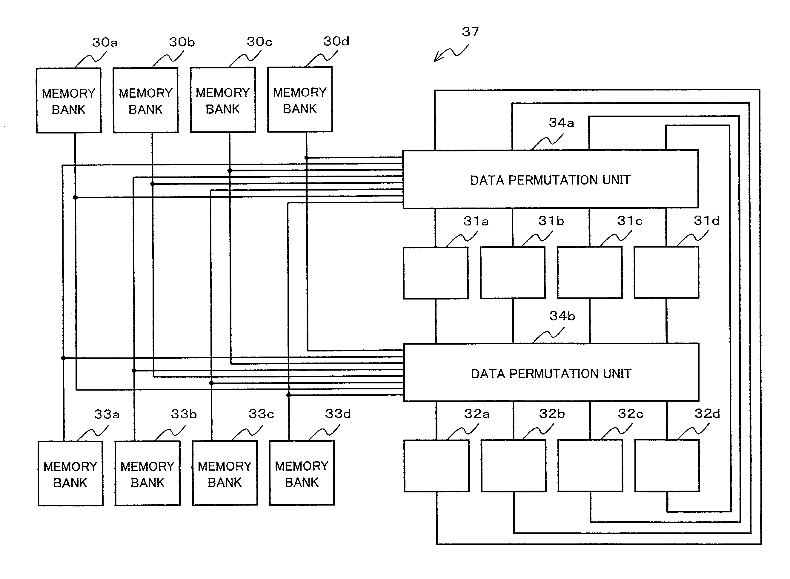
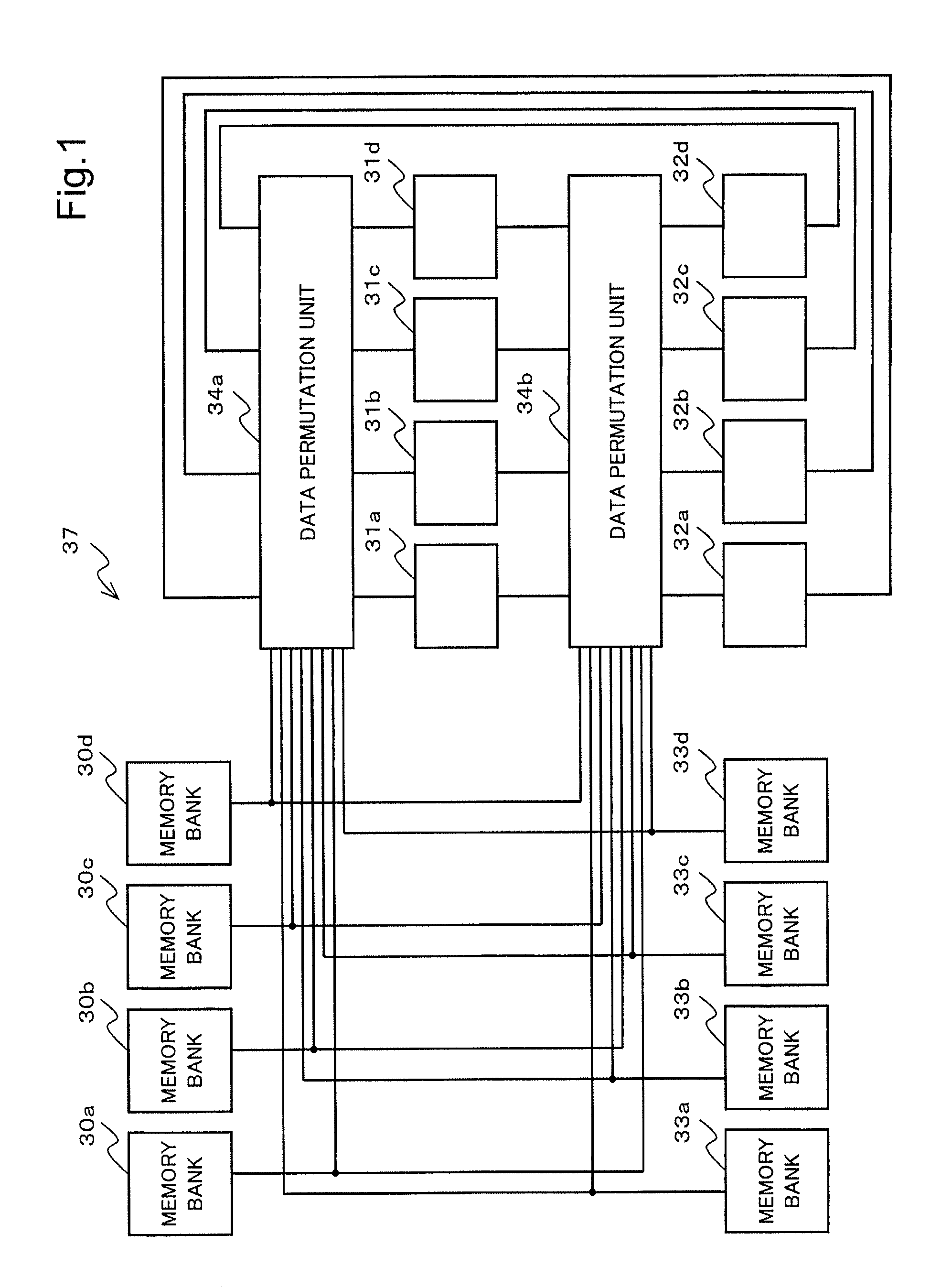
[0036]FIG. 1 is a block diagram illustrating an example of a configuration of a computation device 37 according to a first exemplary embodiment of the present invention.
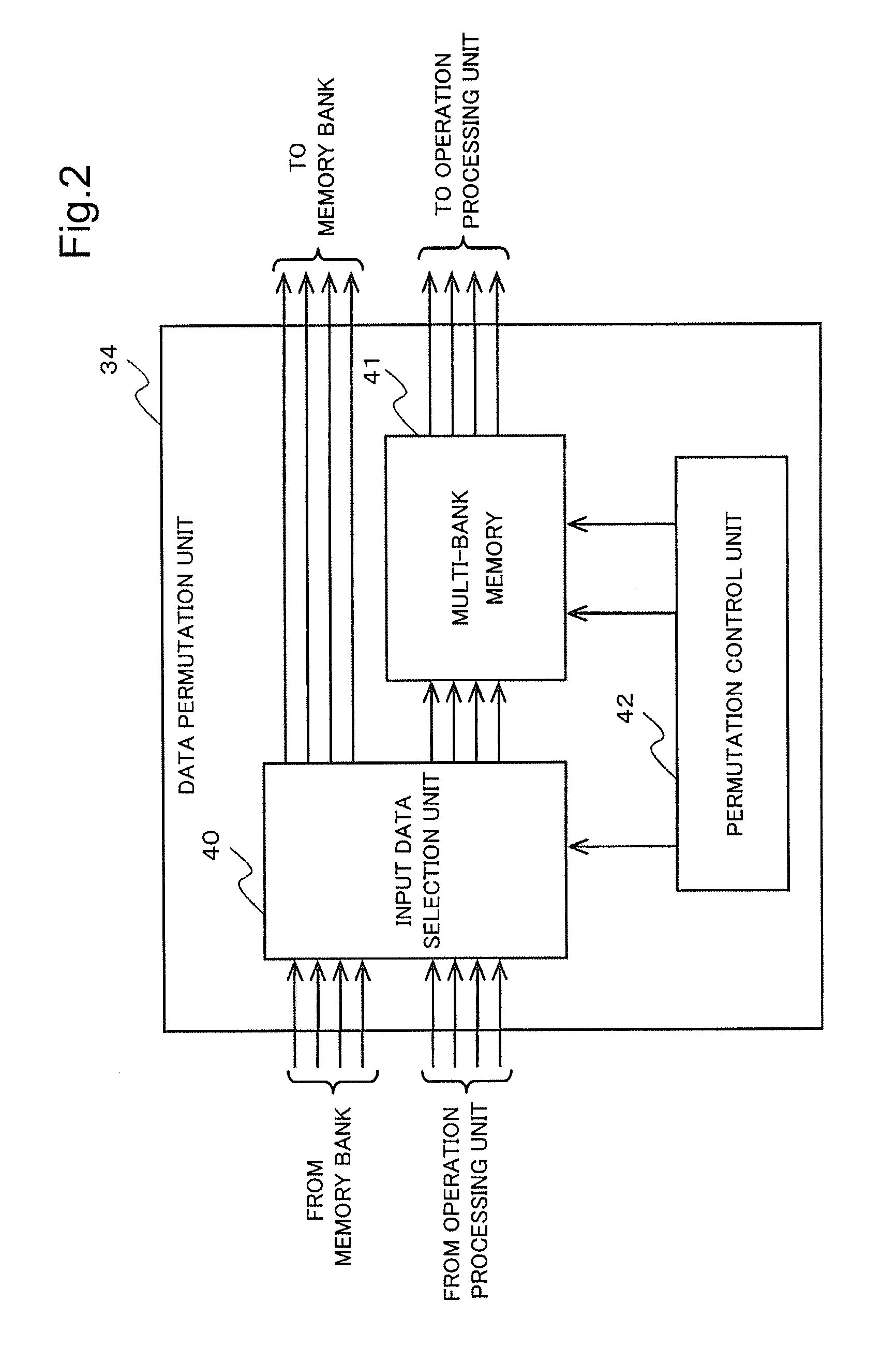
[0037]The computation device 37 includes memory banks 30a to 30d, memory banks 33a to 33d, operation processing units 31a to 31d, operation processing units 32a to 32d, and data permutation units 34a to 34b. Hereinafter, the memory banks 30a to 30d will be collectively referred to as a memory bank 30. In the same manner, the memory banks 33a to 33d will be collectively referred to as a memory bank 33. The operation processing units 31a to 31d will be collectively referred to as an operation processing unit 31. The operation processing units 32a to 32d will be collectively referred to as an operation processing unit 32. The data permutation units 34a and 34b will be collectively referred to as a data permutation unit 34.
[0038]As illustrated in FIG. 1, the computation device 37 according to the present exemplary embodi...
modified example
[0149]The configuration of the computation device 37 is not limited to the above description.
[0150]In the computation device 37, for example, at least a part of the memory bank 30, the memory bank 33, the operation processing unit 31, the operation processing unit 32, and the data permutation unit 34 may be a separate device connected via a network or a bus.
[0151]Further, in the computation device 37, each component may be divided into a plurality of components.
[0152]For example, in the data permutation unit 34, each component may be configured by using a separate device connected via a network or a bus.
[0153]Further, in the data permutation unit 34, a plurality of components may be configured as one component.
[0154]The data permutation unit 34 may be realized, for example, as a computer including a CPU (Central Processing Unit), a ROM (Read Only Memory), a RAM (Random Access Memory), and an interface circuit (IF).
[0155]FIG. 6 is a block diagram illustrating an example of a configur...
second exemplary embodiment
[0164]Next, a computation device 37 according to a second exemplary embodiment of the present invention will be described with reference to the drawings.
[0165]A configuration of the computation device 37 according to the present exemplary embodiment is the same as the computation device 37 according to the first exemplary embodiment, and therefore, description of the configuration is omitted.
[0166]The computation device 37 according to the present exemplary embodiment operates in the same manner as the first exemplary embodiment except that permutation control of the data permutation unit 34 is different. Therefore, description of the same operation is omitted and an operation specific to the present exemplary embodiment will be described.
[0167]The input data selection unit 40 according to the first exemplary embodiment selects input data to an operation processing unit as the posterior stage and selects whether or not to output an operation result to a memory bank, based on a signa...
PUM
 Abstract
Description
Claims
Application Information
 - R&D
- Intellectual Property
- Life Sciences
- Materials
- Tech Scout
- Unparalleled Data Quality
- Higher Quality Content
- 60% Fewer Hallucinations
Browse by: Latest US Patents, China's latest patents, Technical Efficacy Thesaurus, Application Domain, Technology Topic, Popular Technical Reports.
© 2025 PatSnap. All rights reserved.Legal|Privacy policy|Modern Slavery Act Transparency Statement|Sitemap|About US| Contact US: help@patsnap.com


